Head and cap transport parts cannot come off
When transporting the main unit, it is necessary to attach the transportation parts for the head and the cap. If forget to remove this part when unpacking or after transportation and turn on the power, the head unit and cap unit will interfere with this part and become locked, causing a fatal error.
Fatal error can be resolved by removing the transport parts, but depending on the mechanical state, it may not be possible to remove the transport part. In this case, it is necessary to change the positions of the head unit and the cap unit by following the procedure below.
 Note / 補足 Note / 補足 |
|
When checking the device status
Turn off the power and check if the transportation part for the head and cap can be removed or not.
Note / 補足- Head Transportation Part
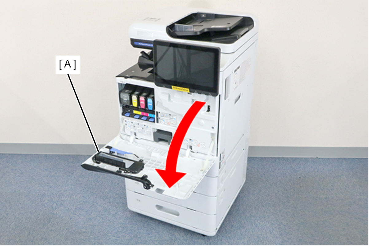
Open the front cover, hold the handle of the transport parts, and pull it forward while rocking it left and right.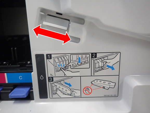
- Head Shaft Transportation Parts
Set the paper in advance to prevent ink stains, inserting your hand inside the curve of the transportation part at the ink cartridge insertion part, rotate it upward and pull it out.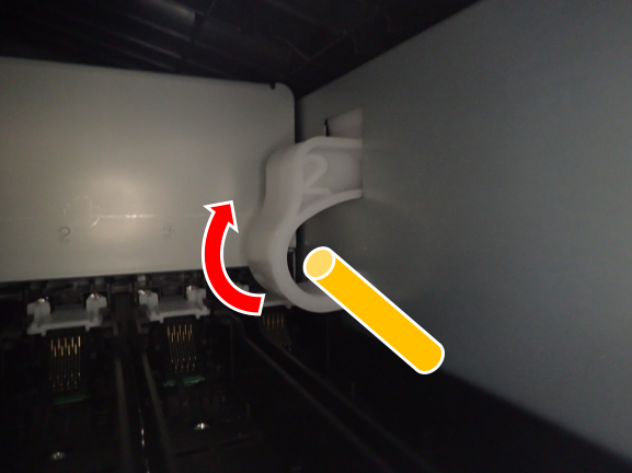
Cap Transportation Part
Open the right door unit and belt unit, and push the handle of the transport parts to the rear.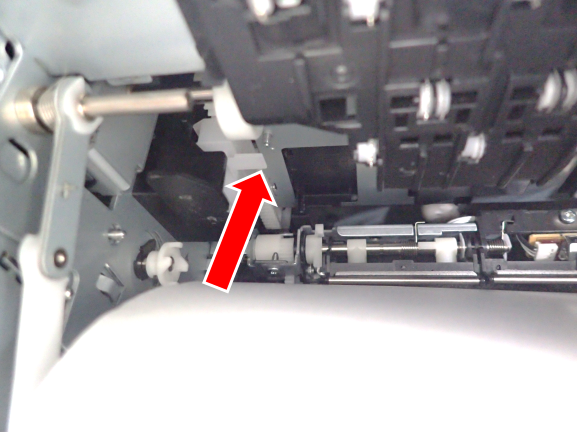
- Head Transportation Part
- Change the position of the head unit or cap unit according to the transport part that could not be removed.
Cap transport parts cannot come off
- Start the service support mode from the power off stateAutomatically Release. If the transportation parts cannot be removed after execution, proceed to the next step.
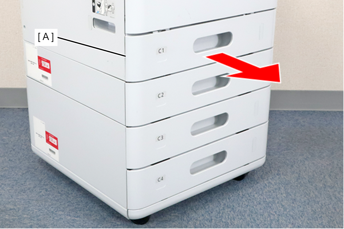
- Remove the C1 cassette (A).
- Open the Front Cover (A).
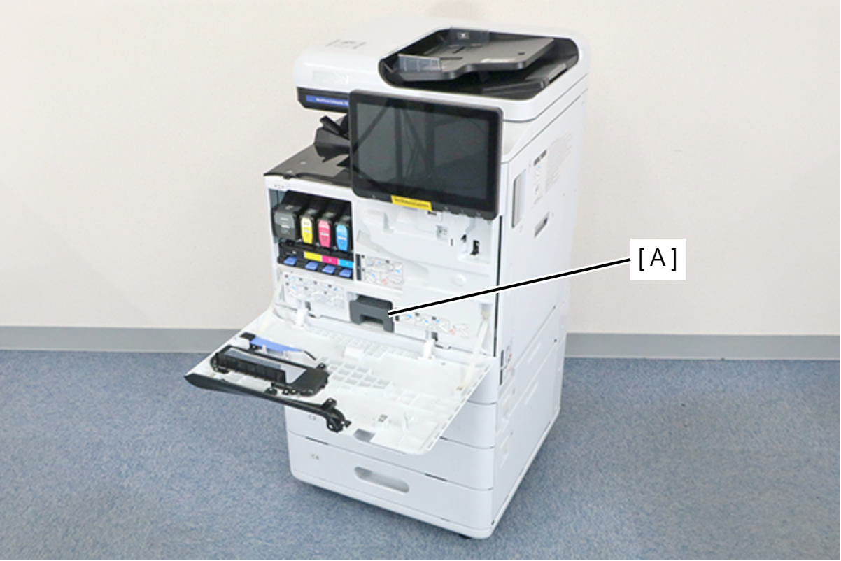
- Remove the Maintenance Box (A).
- Remove the 7 screws and remove the Front Inner Cover (A).
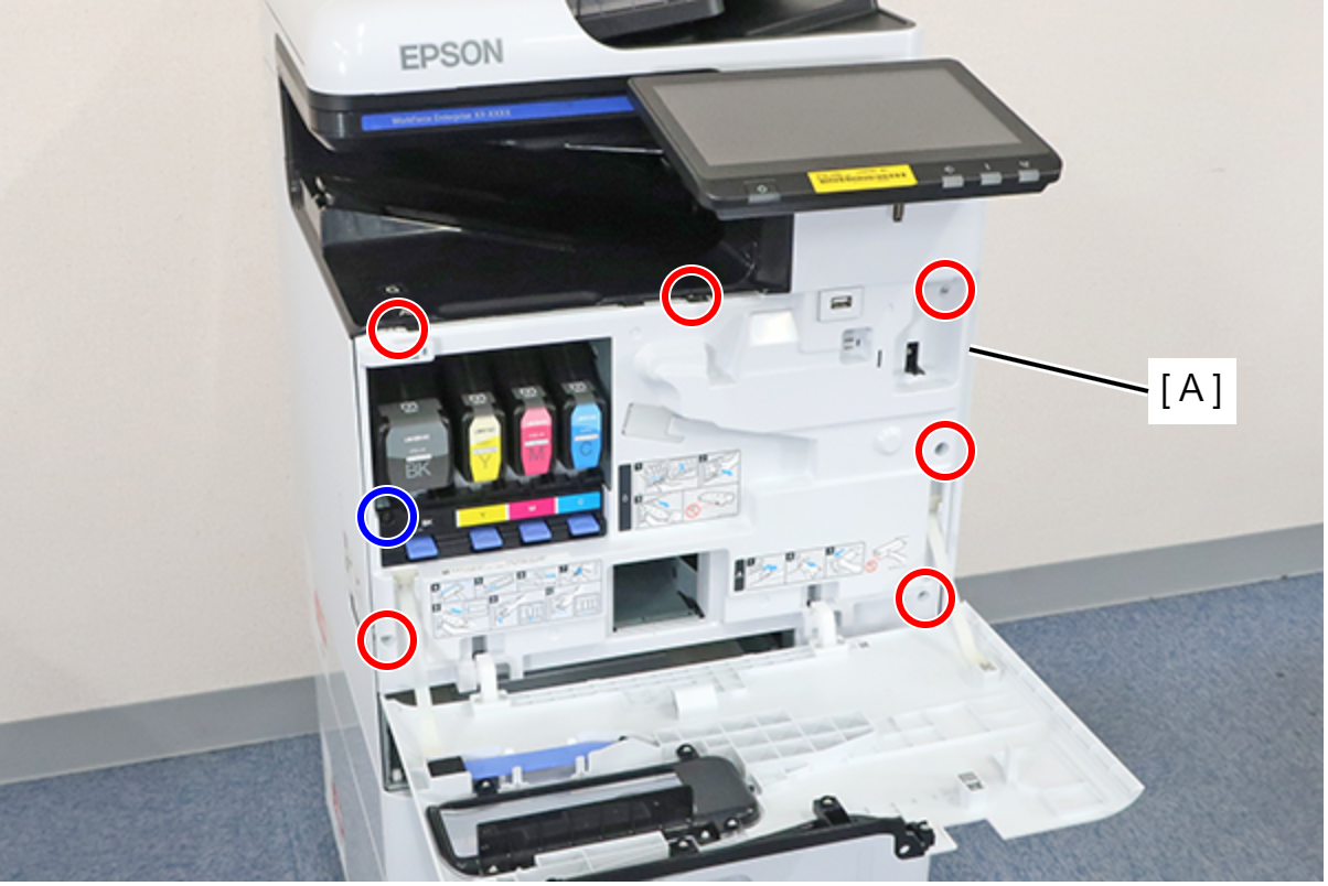
 : 3x8D
 : 3x8D/BK
 Assembly / 組み立て
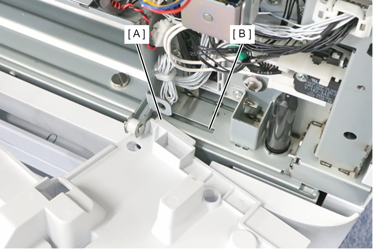
Insert the protrusion (A) of the Front Inner Cover into the hole (B) of the main unit and install.
- Change the position of the cap unit by turning the dial (A) of the cap drive motor.
- Turn the dial clockwise (UP direction) 1/4 turn. If you can't rotate it, rotate it 1/4 turn counterclockwise.
- Try to remove the cap transport parts. If it cannot be removed, rotate it another 1/4 turn.
- After that, repeat until it comes off.
- Turn the dial clockwise (UP direction) 1/4 turn. If you can't rotate it, rotate it 1/4 turn counterclockwise.
- Try to remove the cap transport parts. If it cannot be removed, rotate it another 1/4 turn.
- After that, repeat until it comes off.
Head transport parts cannot come off
- Start the service support mode from the power off stateManually Release (Head unit DOWN). If the transportation parts cannot be removed after execution, proceed to the next step.
- Start the service support mode Manually Release (Head unit UP). If the transportation parts cannot be removed after execution, proceed to the next step.
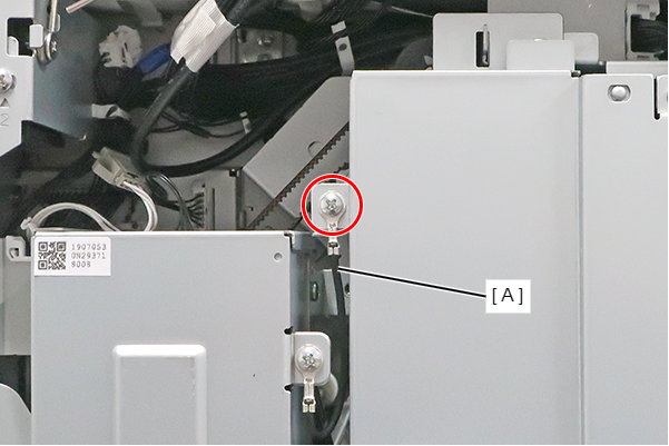
- Remove the 3 screws and remove the Right Cover (A).
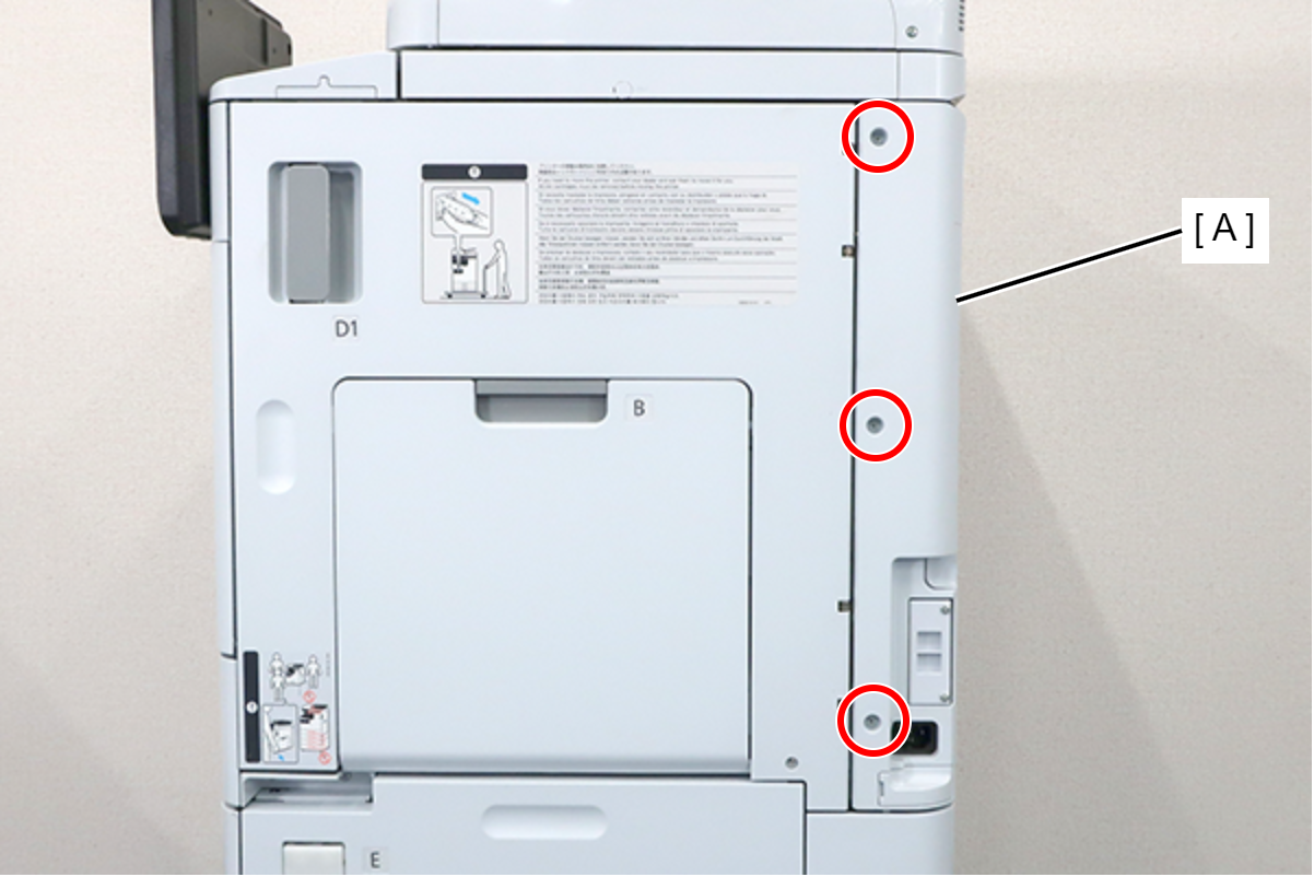
- : 3x8D
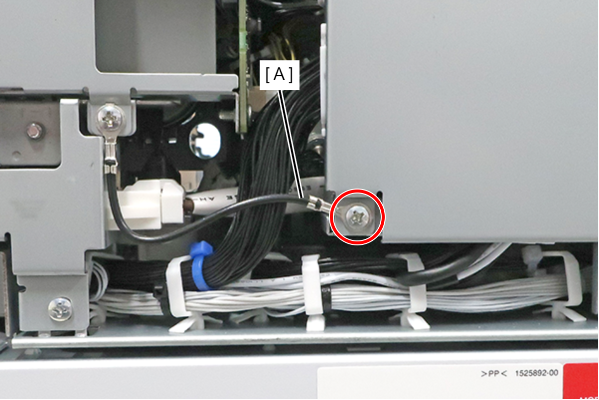
- Remove the 5 screws and pull the rear cover (A) toward to remove it.
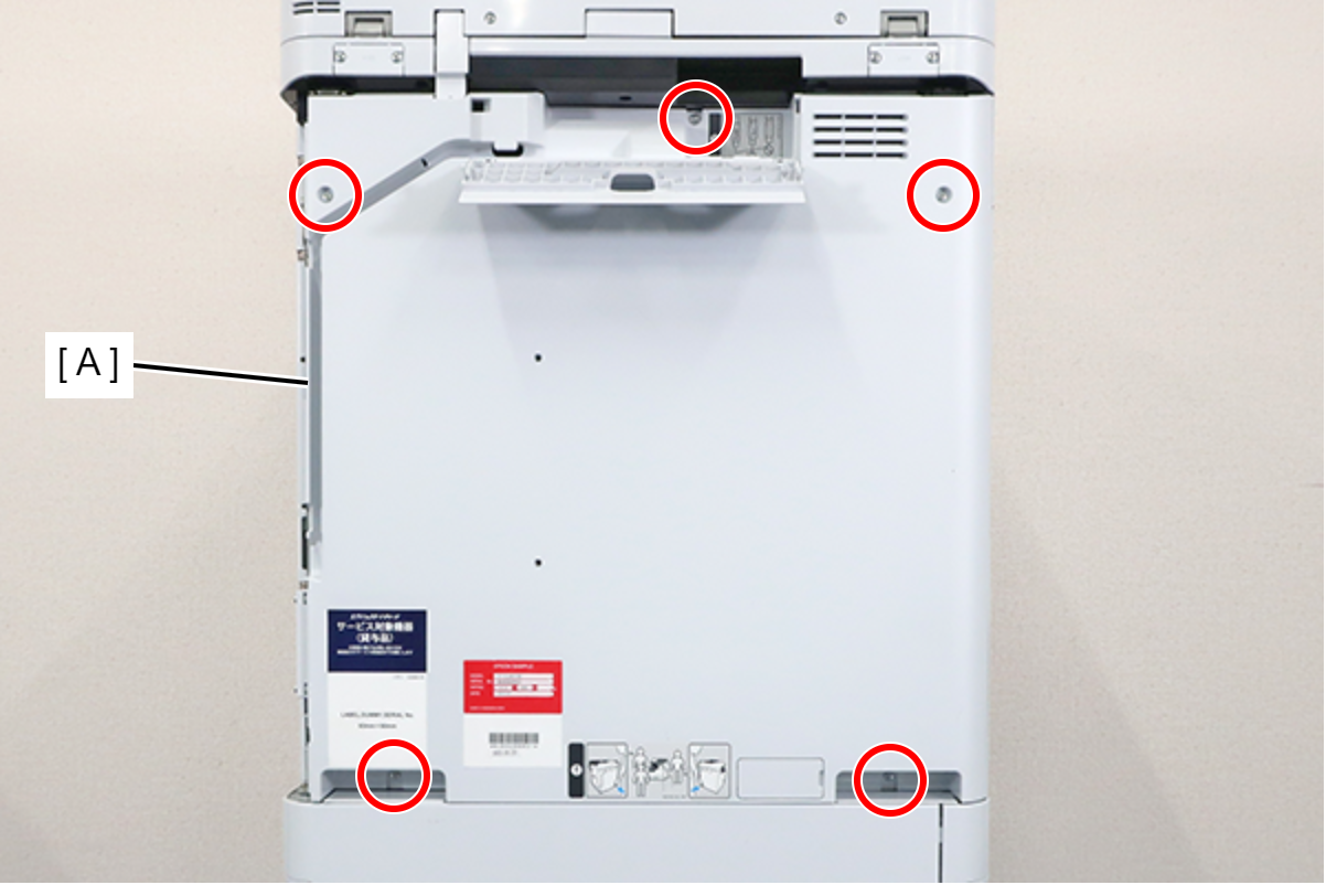
 : 3x8D
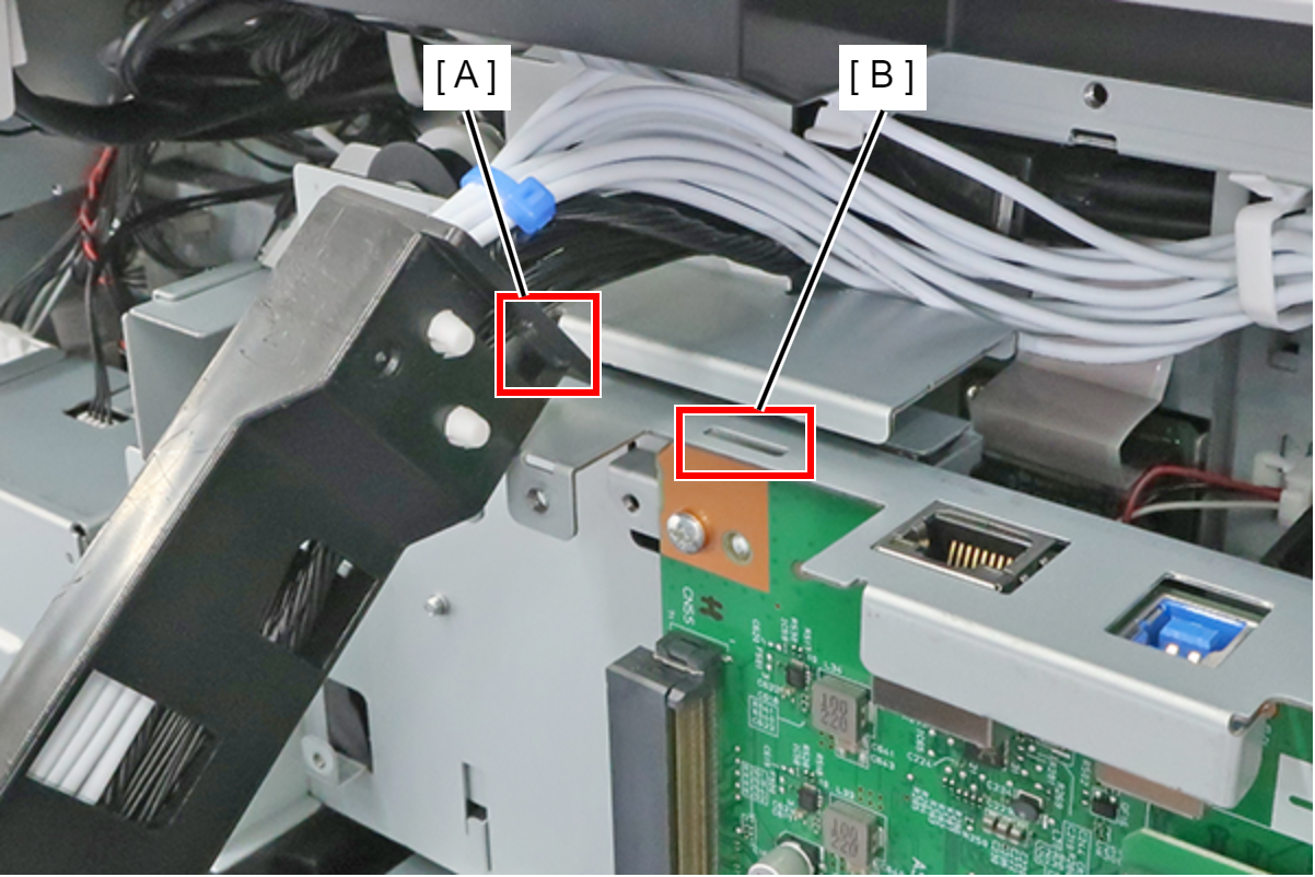
Assembly / 組み立てConfirm that the rear cover is not floating. The positioning pin (A) may not fit into the hole (B).

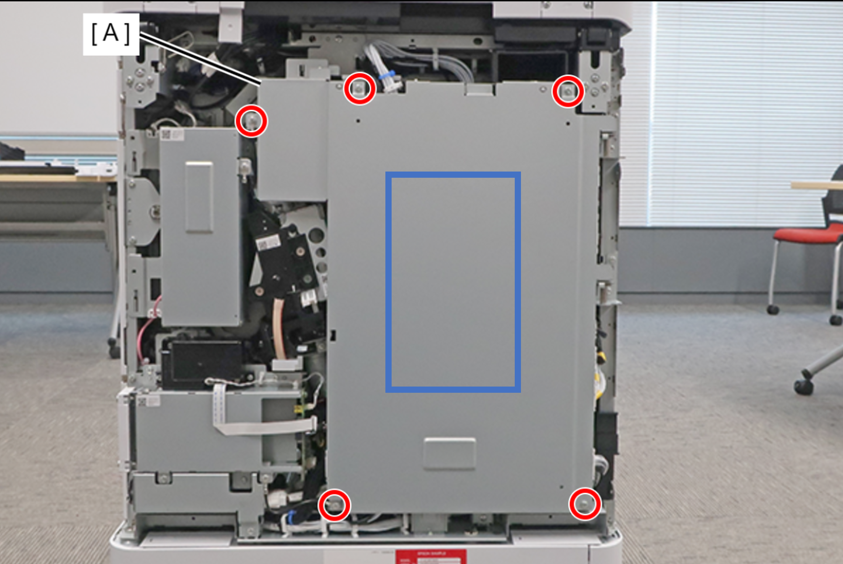
- Remove the 5 screws fixing the Main Board Cover (A).
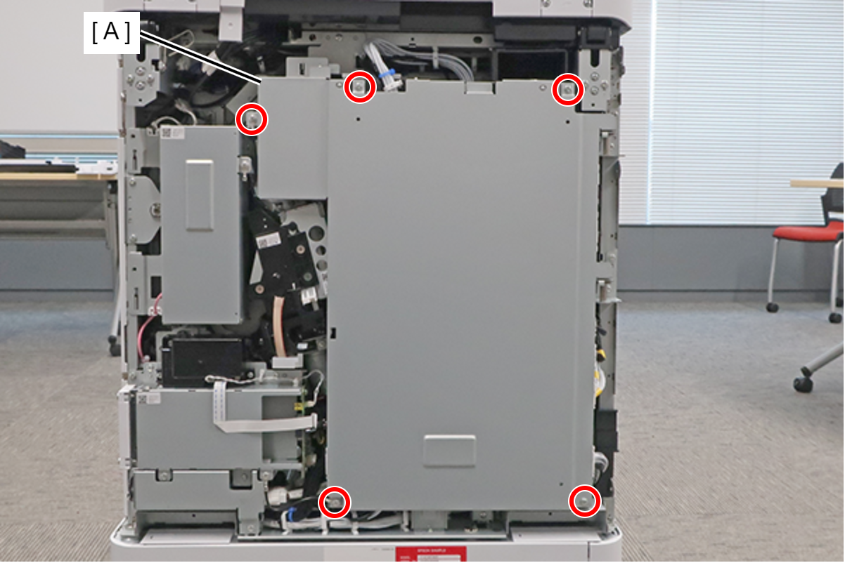
 : 3x8D
Assembly / 組み立てThe screw shown in the figure must be fastened together with the ground wire (A).
When installing the Main Board Cover, hold the center part with your hand while tightening the screws to prevent the cover from lifting.
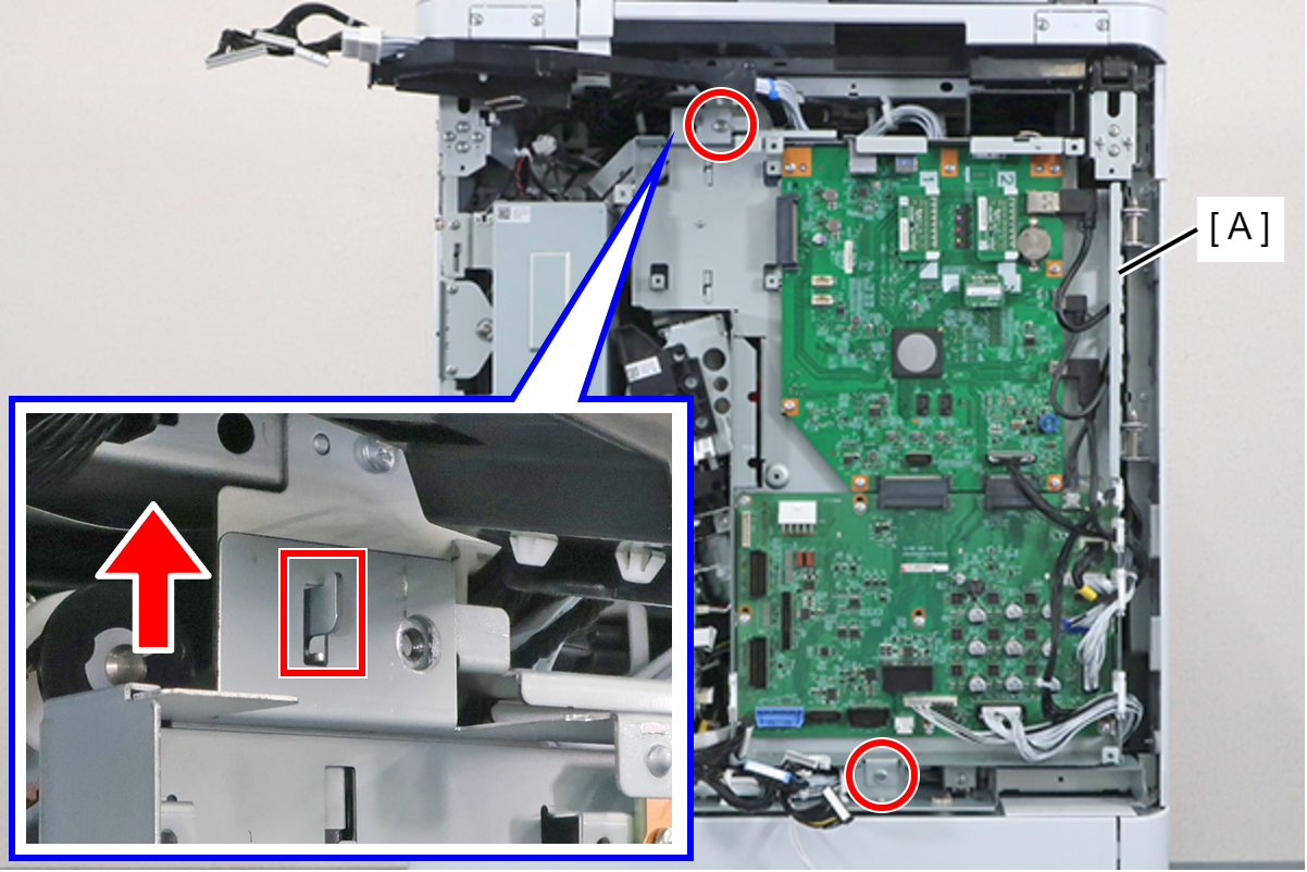
Lift the main board cover (A) slightly to release the dowel (B) and open the main board cover (A).
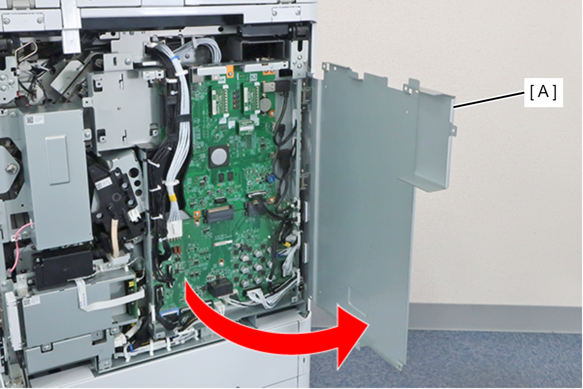 Note / 補足
The Main Board Cover (A) can be completely removed by lifting it in the open position shown above.
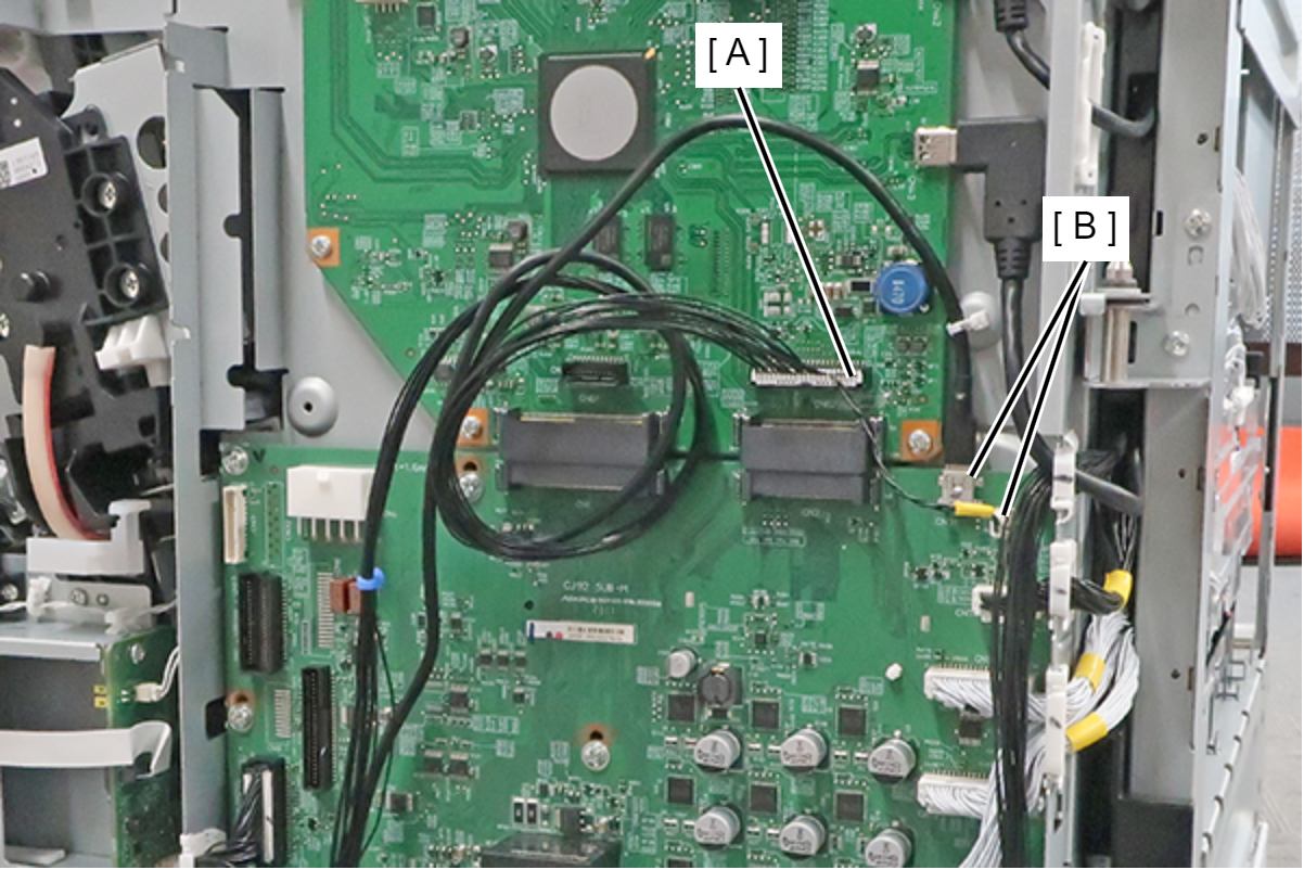
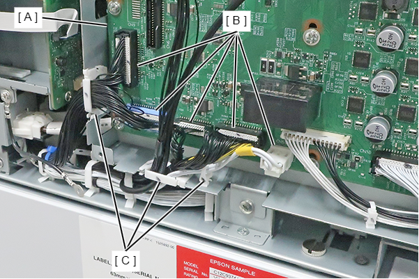
- Disconnect the cables from the connectors (B) (CN3/CN4/CN6/CN13) of the MCU Board (A), and remove the screw. Remove the clamp (C).
- : 3x8D
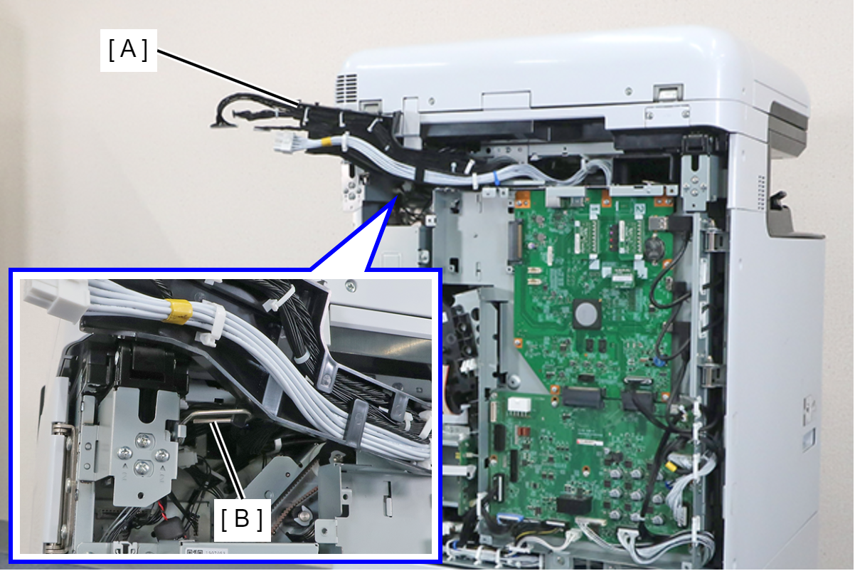
Hang the protrusion of the MCU Wiring Rail (A) on the Wire Hook (B), and withdraw it.
 Assembly / 組み立て
Engage the hook (A) of the MCU Wiring Rail in the hole (B) of the Board Box and install.
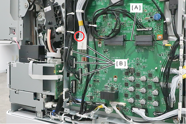
- Disconnect the cables from the main board connector (A), the MCU board connectors (B) and release from clamp (C).
- Disconnect the cables (CN5/CN10/CN11/CN12/CN504) from the connector (B) of the MCU Board (A), and release the from the 3 clamps (C).
- Remove the 2 screws, slightly lift the board box (A) to release the hook.
- : 4x8D
Open the Board Box (A), and fix with the Wire Hook (B).
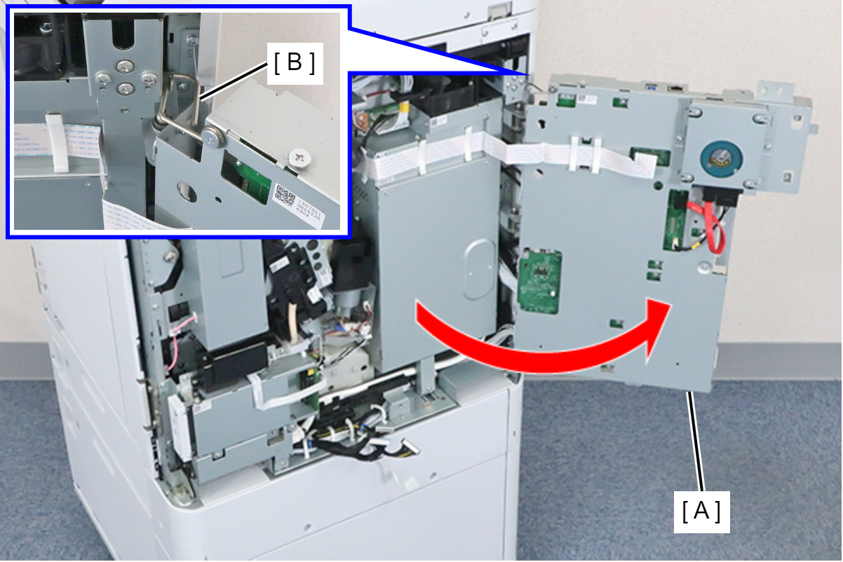
 Caution / 注意
Be careful not to close the Board Box with the Wire Hook fixed in place.
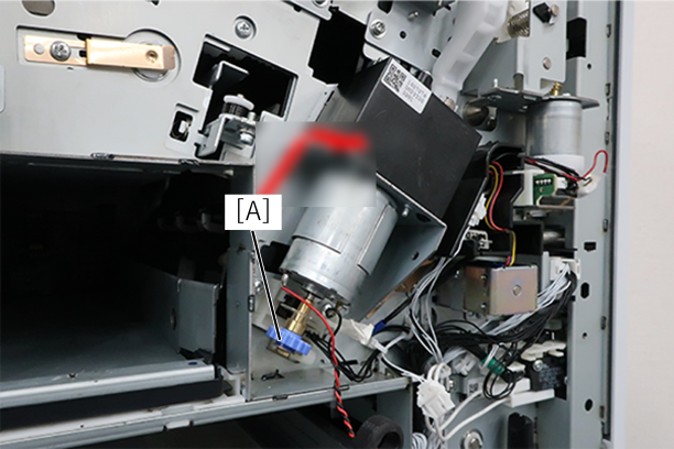
- Change the position of the head unit by turning the dial (A) of the head drive motor.
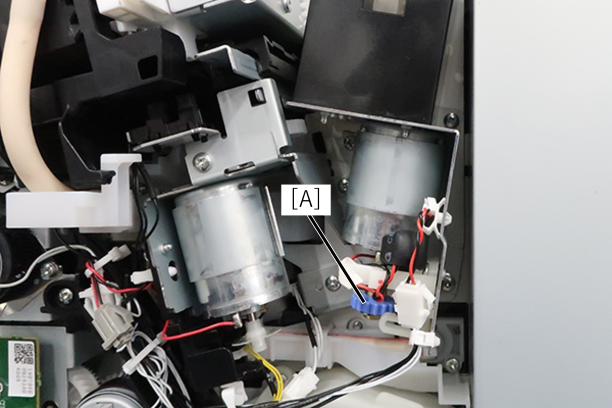
- Turn the dial clockwise (DOWN direction) 1/4 turn. If you can't rotate it, rotate it 1/4 turn counterclockwise.
- Try to remove the transport part for the head. If it cannot be removed, rotate it another 1/4 turn.
- After that, repeat until it comes off.
- Turn the dial clockwise (DOWN direction) 1/4 turn. If you can't rotate it, rotate it 1/4 turn counterclockwise.
- Try to remove the transport part for the head. If it cannot be removed, rotate it another 1/4 turn.
- After that, repeat until it comes off.