Additional HDD Installation Procedure
 important / 重要 important / 重要 |
|
Bundled Items

| No. | Bundled Item | Qty |
|---|---|---|
| 1 | Additional HDD | 1 |
| 2 | Raid Unit | 1 |
| 3 | SATA Cable | 1 |
| 4 | Cable | 1 |
| 5 | Small Screw | 4 |
Installation Procedure
Items to Prepare
- Gloves
- Phillips (+) screwdriver
Minimum number of workers
1 person
 Caution / 注意 Caution / 注意 |
Be sure to check the following precautions before installation.
|
Installation Procedure
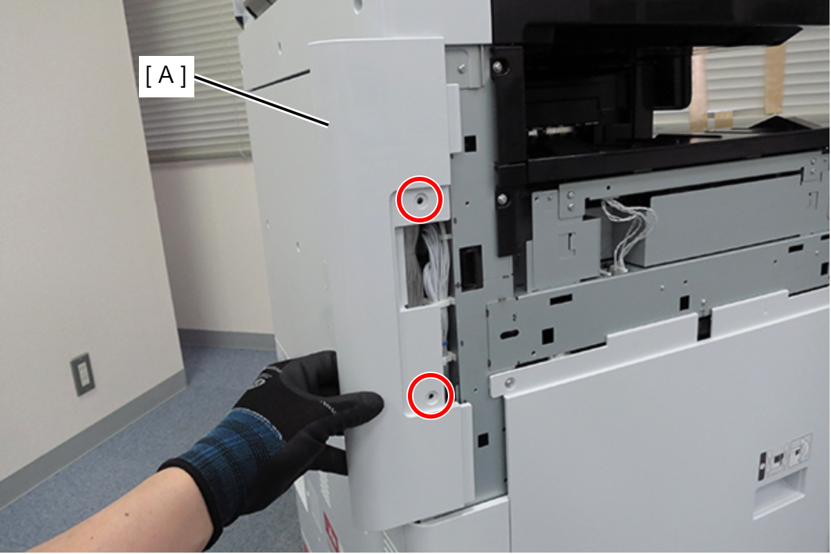
- Remove the 2 screws and remove the left cover upper (A).
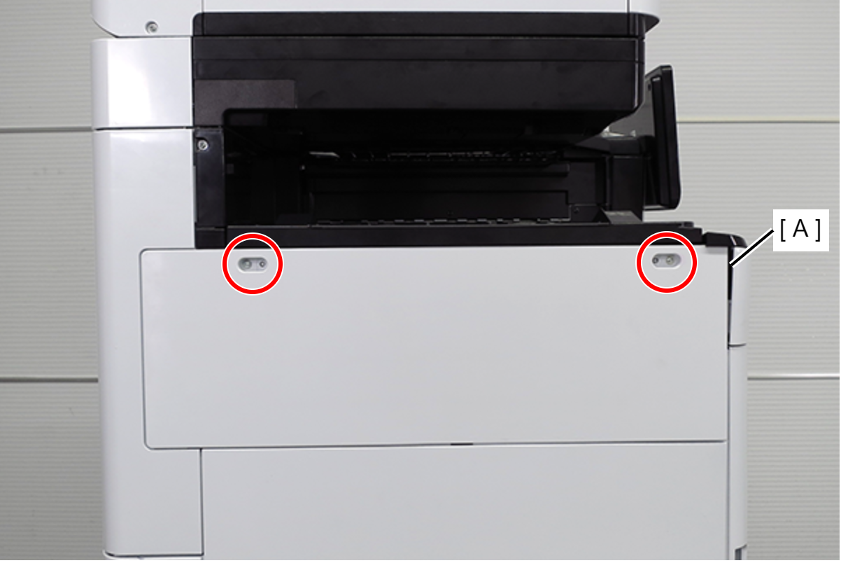
 : 3x10DC/P
 - Remove the two screws and slide the upper left cover sub (A) in the direction of the arrow to remove it.
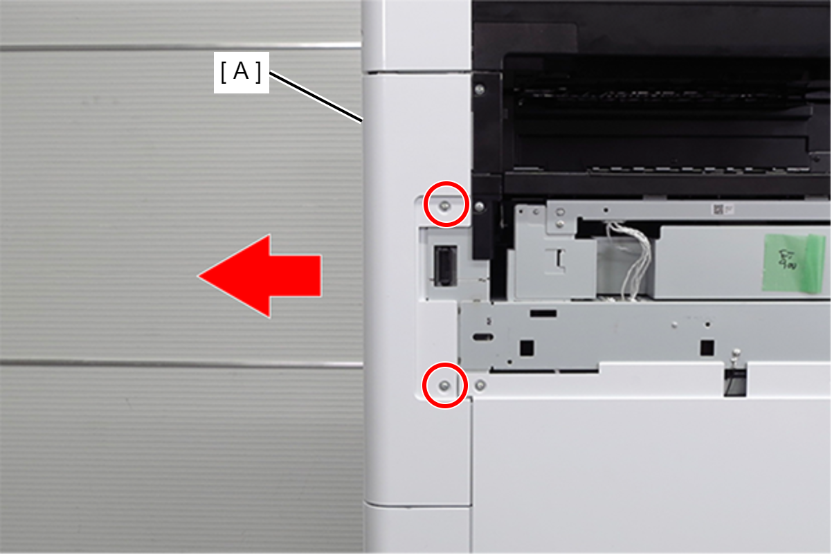
 : 3x10DC/P
- Remove the 4 screws and remove the right cover sub (A).
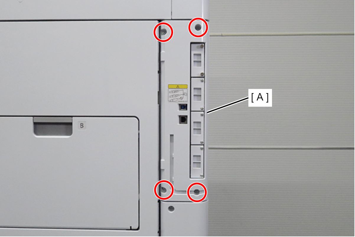
- : 03x10DC/P
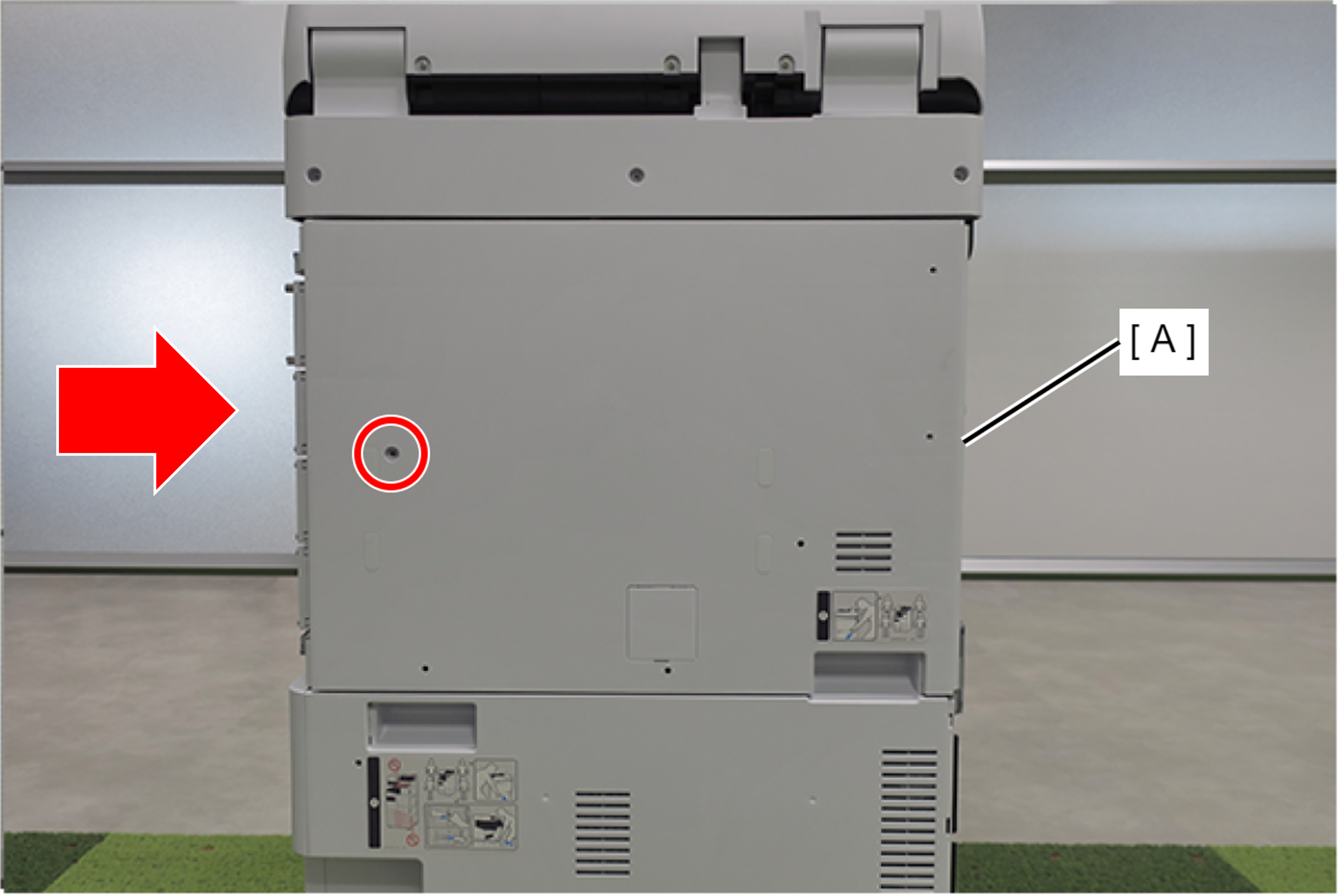
- Remove 1 screw and slide the rear cover (A) in the direction of the arrow to remove it.
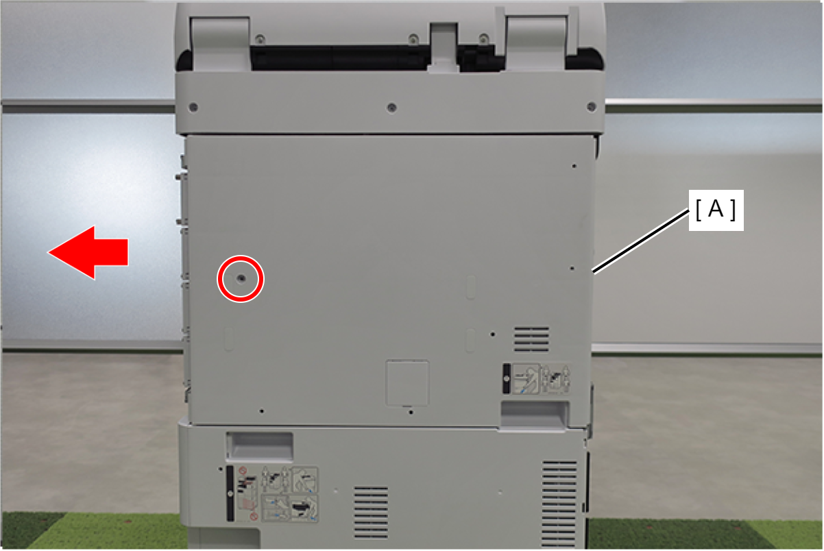
- : 3x10DC/P
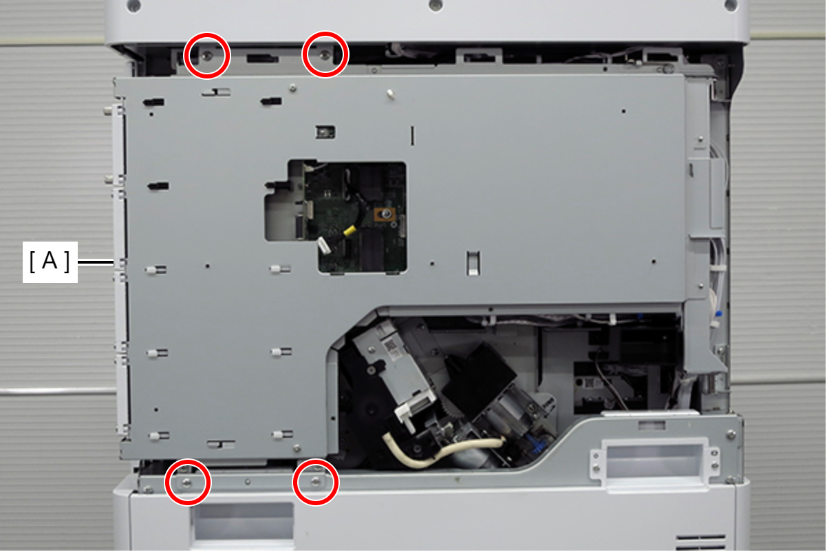
- Remove 4 screws.
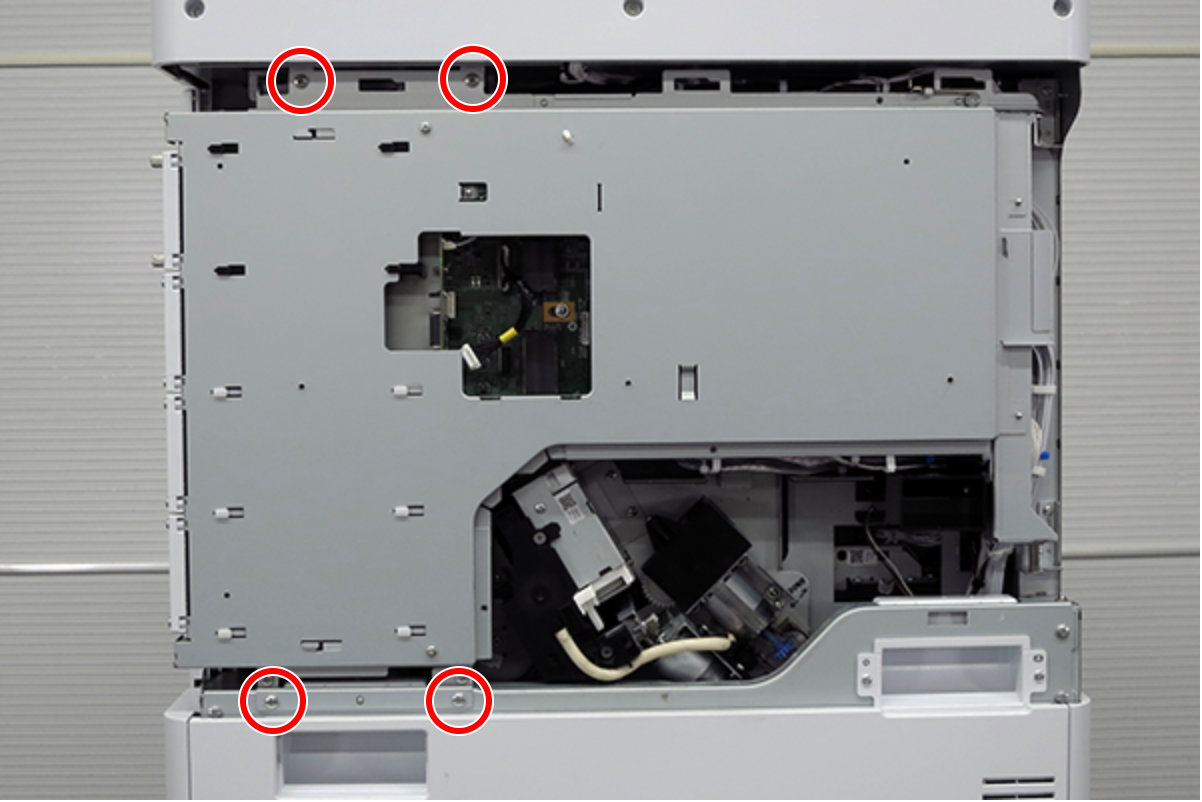 : 4X8D
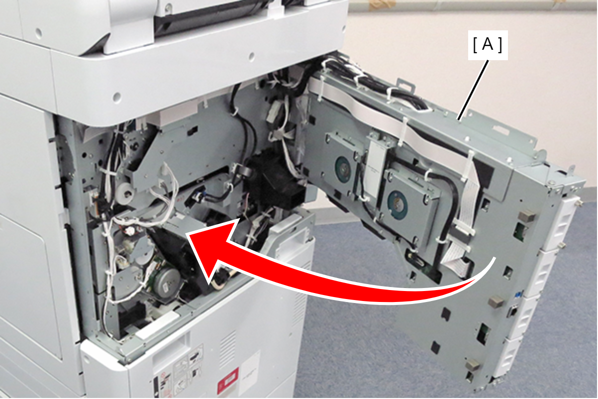
- Slightly lift the board box (A) to release the hook.
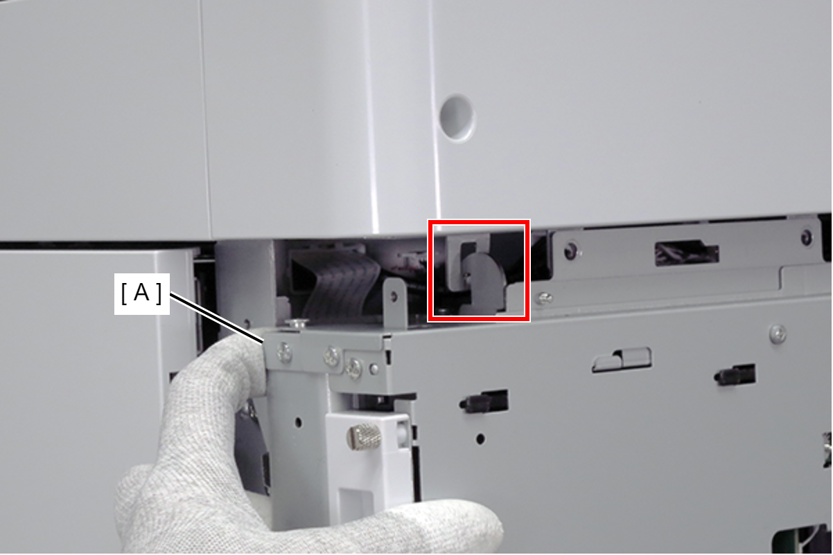
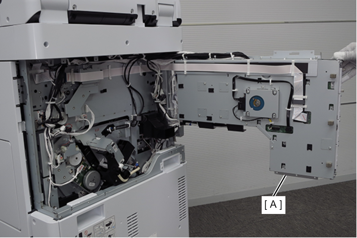
Open the board box (A).
 Check Point / チェックポイント
By hooking the hook (A) of the board box to the hole in the main body, the position of the board box is stabilized, making it easier to work.
- Remove the 4 screws and remove the 4 mounting hole protection plates (A) for the additional HDD.

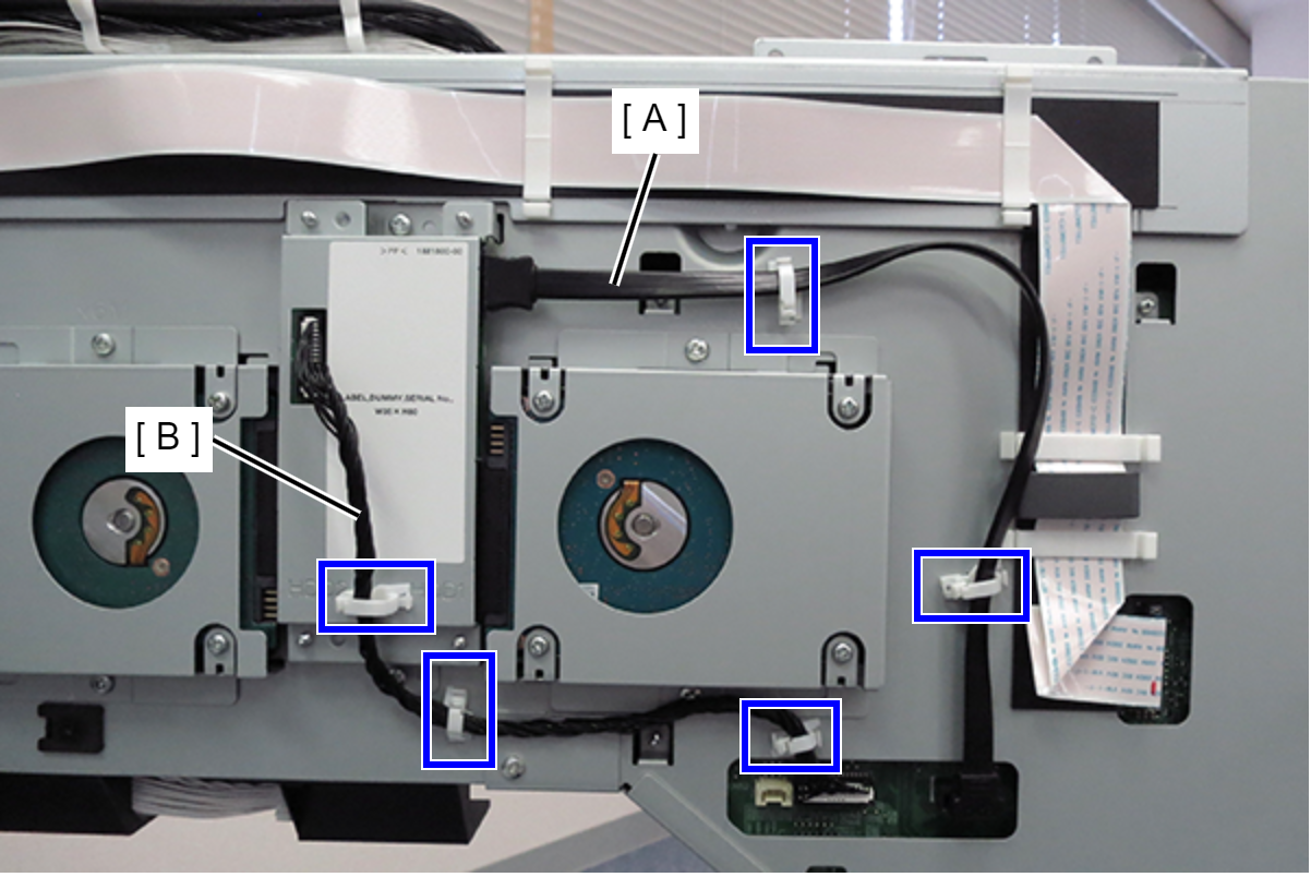
- Release the cables from the 5 clamps on the board box.
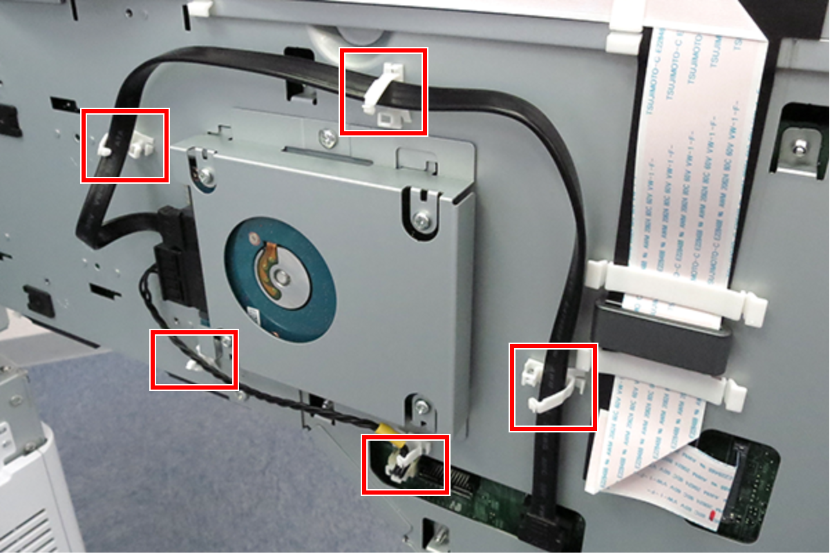
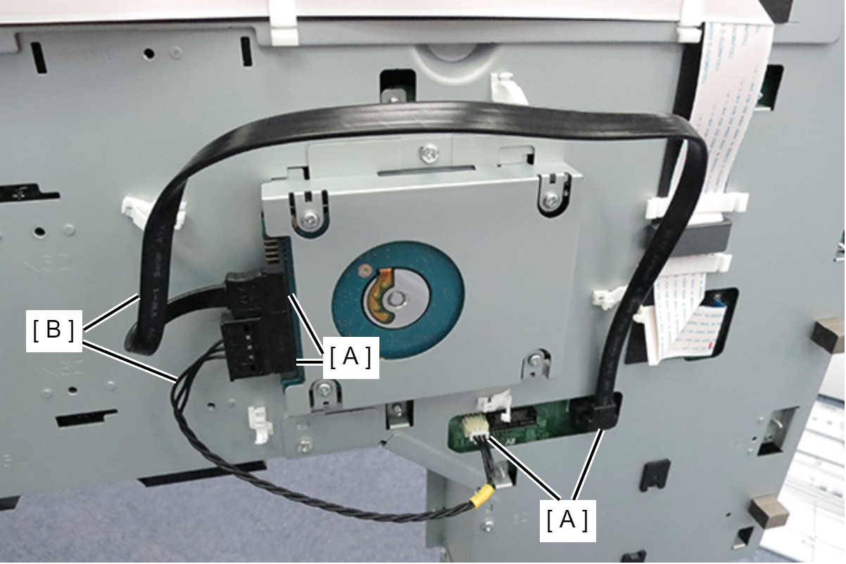
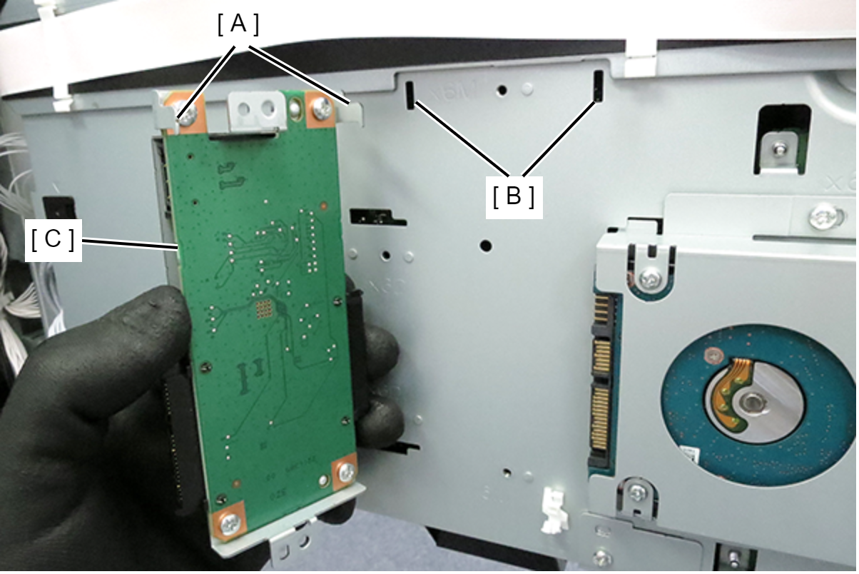
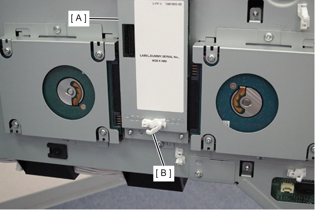
- Disconnect the cables from the connectors (A) on the HDD and main board, and remove the two cables (B).
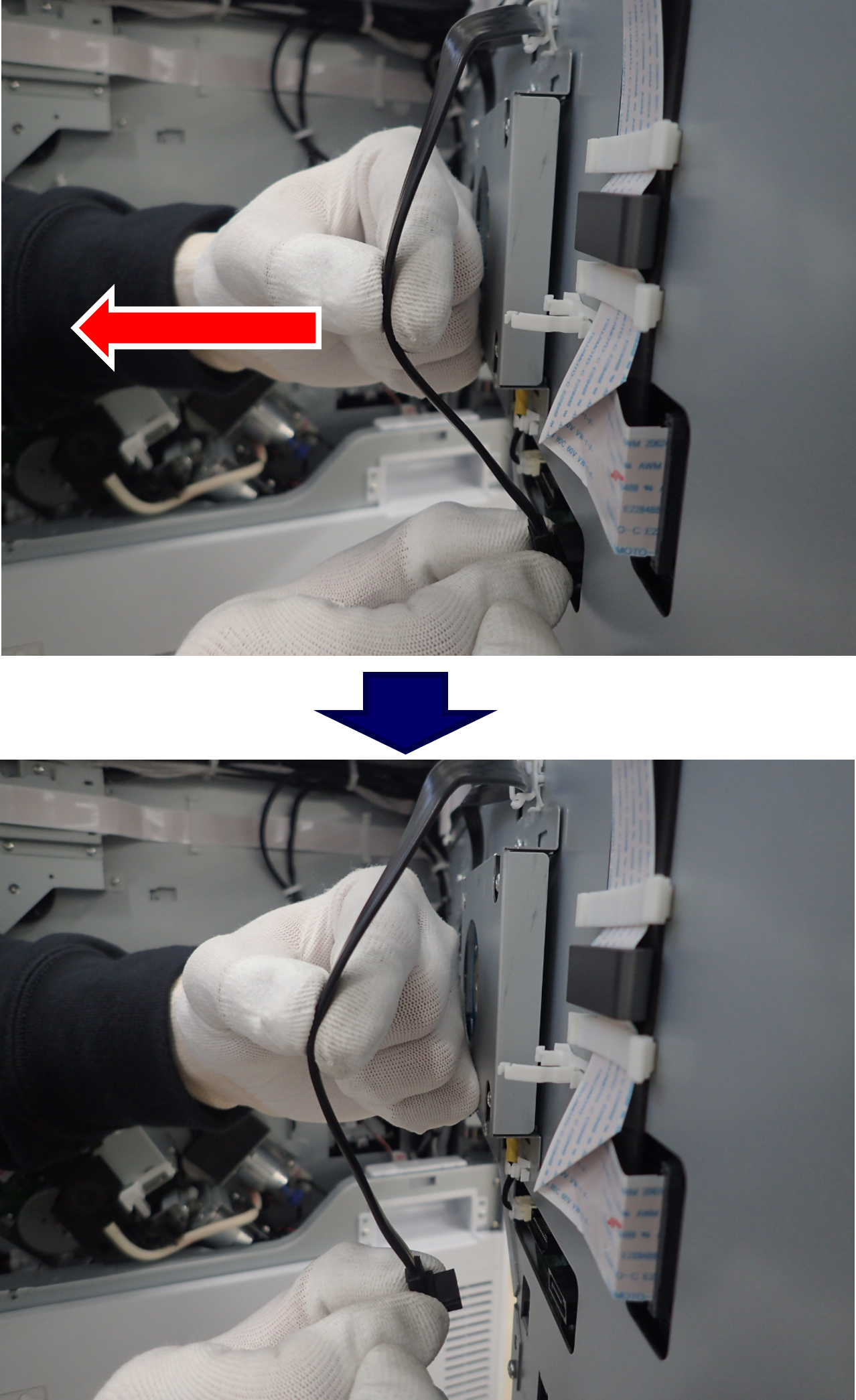
 Caution / 注意
When remove the SATA cable (right side), hold the position shown in the figure with fingers and pull horizontally in the direction of the arrow. At this time, support the connector with fingers so that it does not fall down.
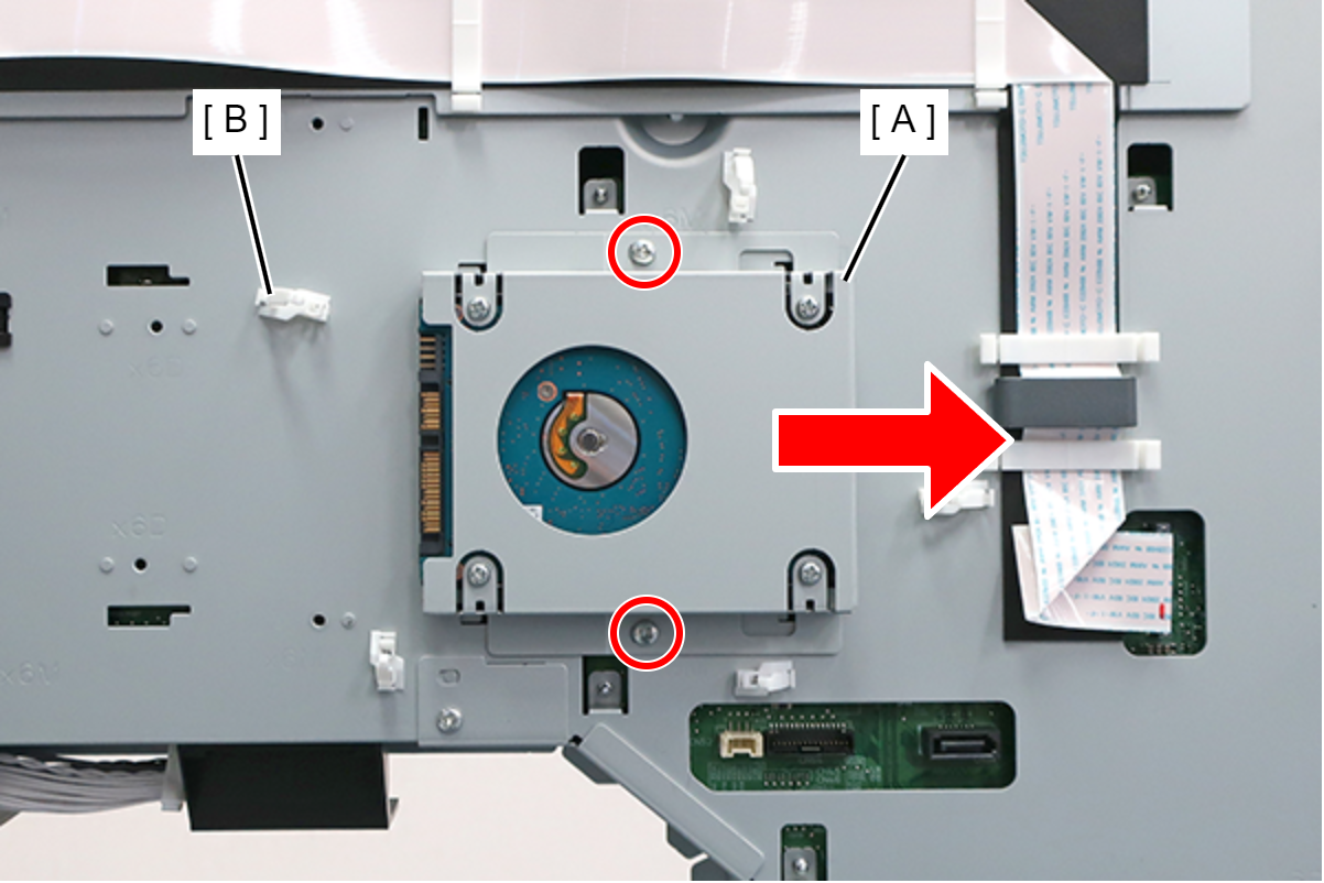
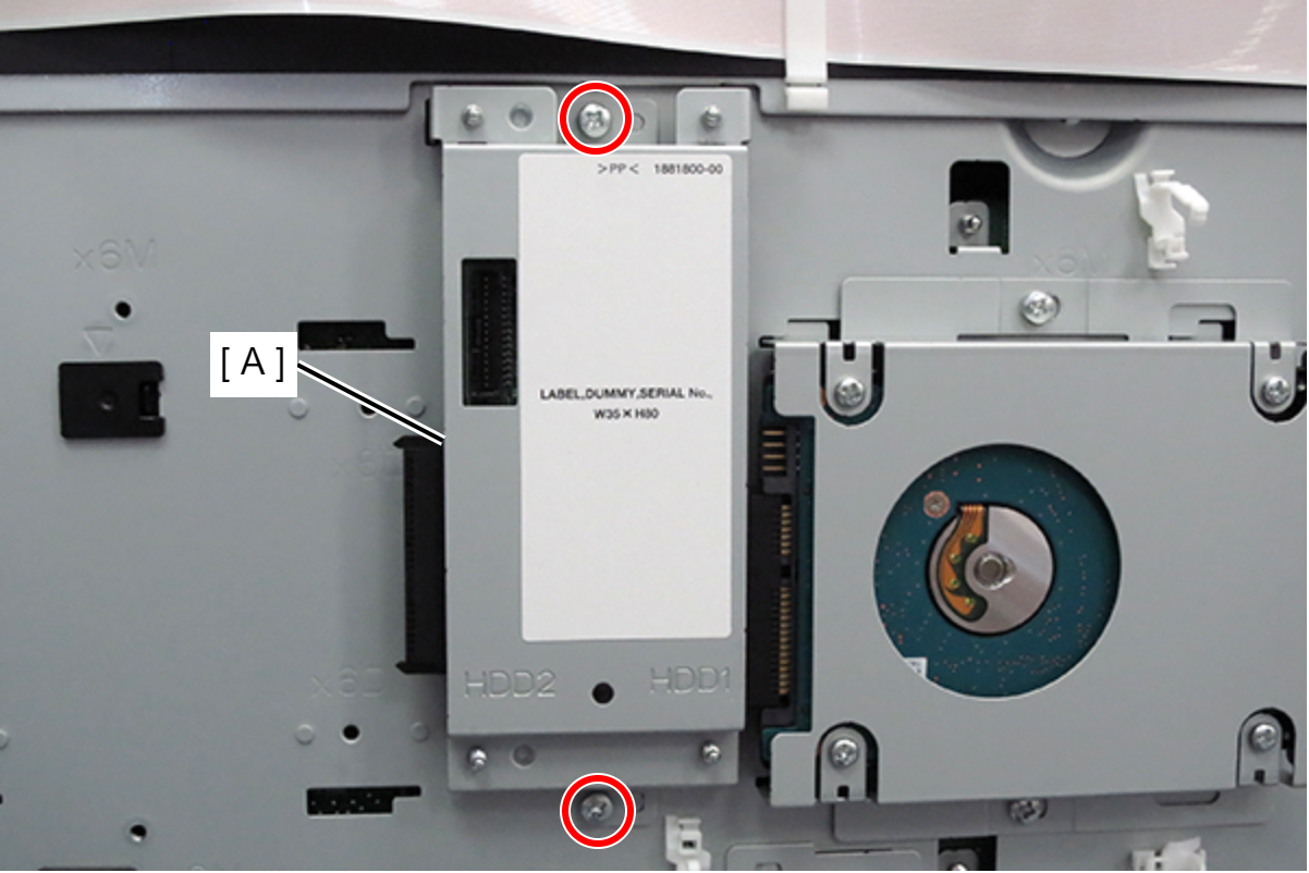
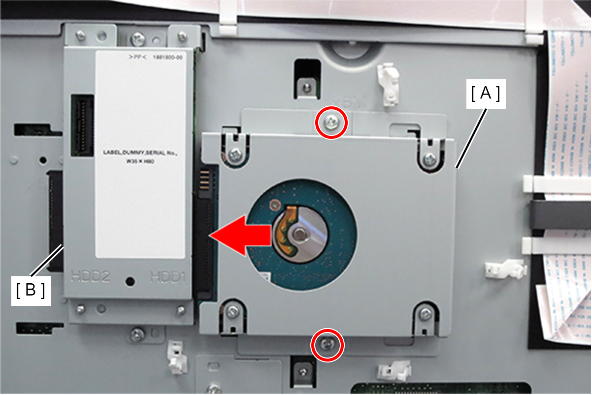
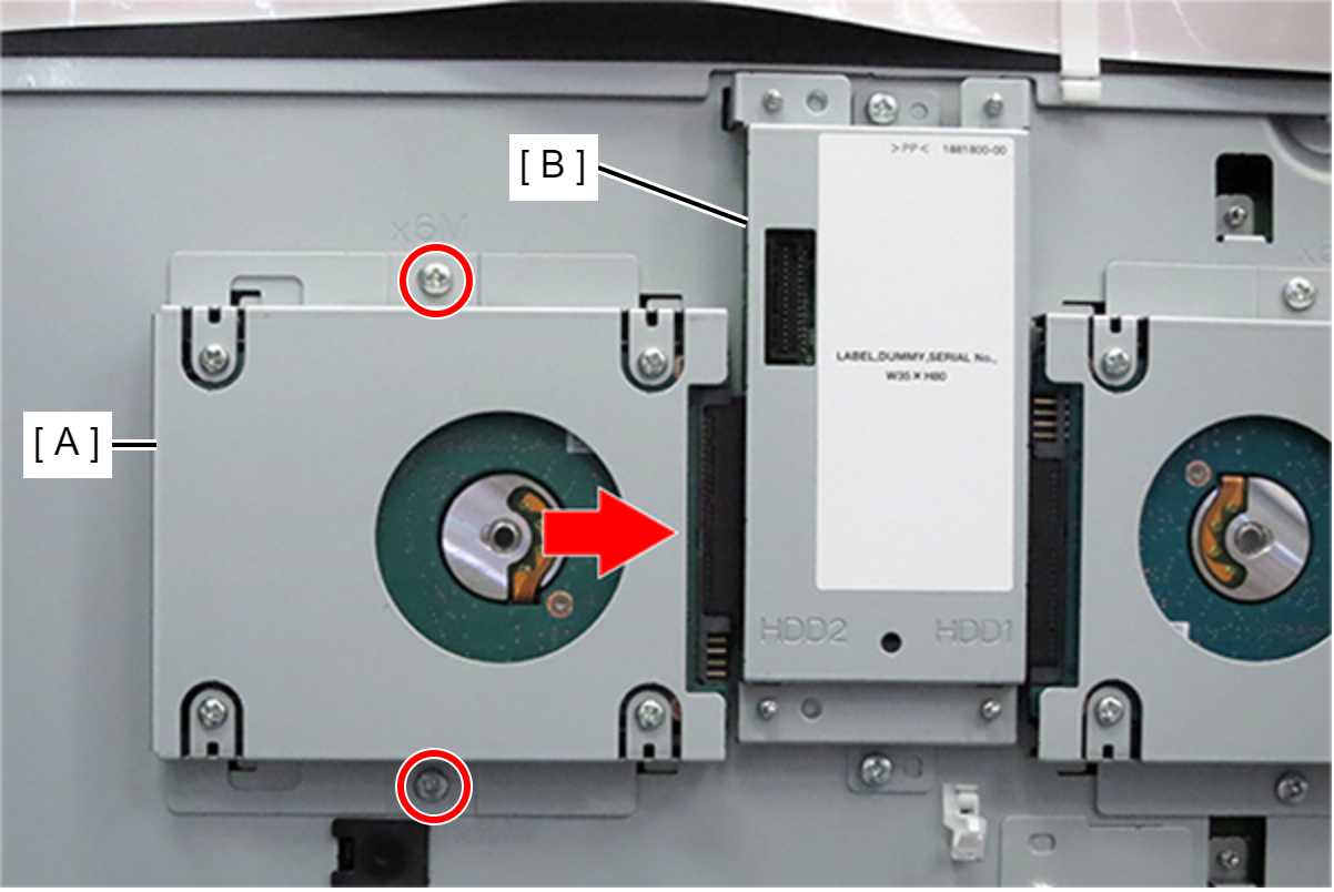
- Loosen the 2 screws that secure the HDD (A), slide to the right, and remove the Clamp (B).
- Hook the 2 hooks (A) of the Raid unit to the 2 holes (B) of the board box, and attach the Raid unit (C).
- Align the dowels with the 2 positioning holes, and secure the Raid unit (A) with 2 screws.
- : 3x6D/P
- Slide the HDD (A) in the direction of the arrow to connect the Raid unit (B), and tighten the 2 screws to fix the HDD.
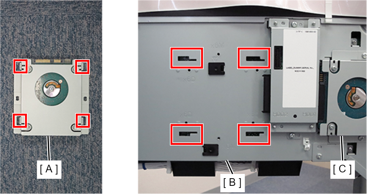
- Hook the 4 hooks of the Additional HDD (A) to the 4 holes of the board box (B), and attach the Additional HDD (A).
- Slide the Additional HDD (A) in the direction of the arrow to connect it to the Raid unit (B), and secure the Additional HDD with 2 screws.
- : 3x6D/P
- Attach the clamp (B) to the Raid unit (A).
- Connect the SATA cable (A) and cable (B) to the Raid unit and main board connectors, and fix with 5 clamps.
- Close the board box (A).
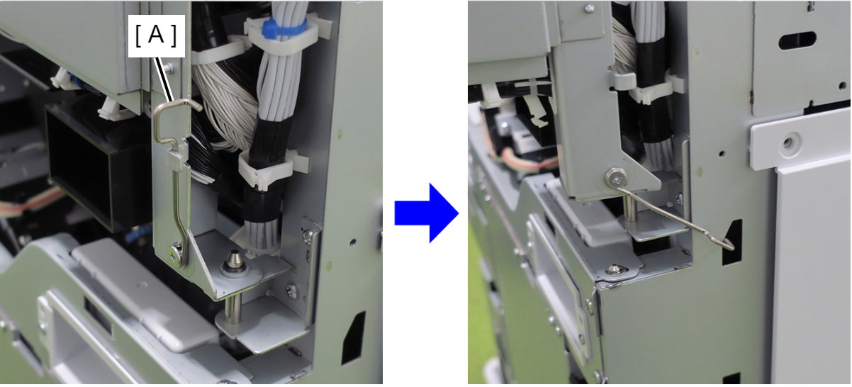
 Check Point / チェックポイント
If the hook (A) of the circuit board box is hung on the main unit, be sure to return to its original position before closing the circuit board box.
Slightly lift the circuit board box (A), hook the hook into the groove on the main unit, and lock.
- Secure the board box (A) with 4 screws.
- : 4x8D
- Align the 5 hooks on the rear cover with the 5 holes on the main unit and attach.
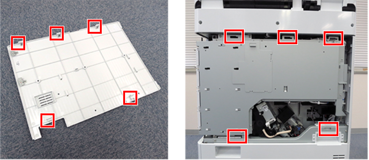
- Slide the rear cover (A) in the opposite direction of the arrow to hook it, and secure with 1 screw.
- : 3x10DC/P
- Install the right cover sub (A) and secure with 4 screws.

- : 3x10DC/P
- Insert the 2 tabs of the left cover sub (A) into the main unit to attach, and secure with 2 screws.
- : 3x10DC/P
- Align the 3 hooks (A) on the left cover upper with the 3 holes (B) on the main unit, and attach the left cover upper (C).
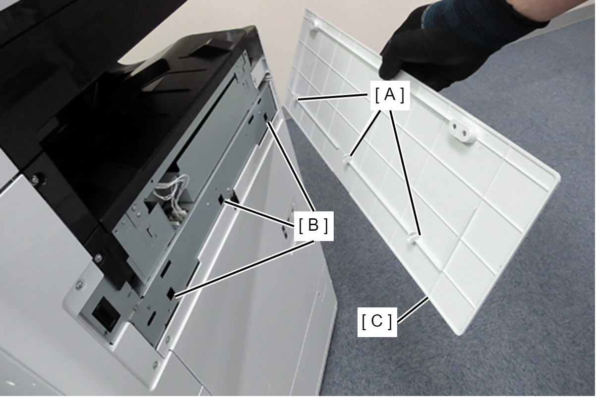
- Secure the left cover upper (A) with 2 screws.
- : 3x10DC/P