Floor Punch Unit Installation Procedure
 Caution / 注意 Caution / 注意 |
Be sure to check the following precautions before installation.
|
Items to Prepare
- Floor Punch Unit Bundled Items
- Phillips (+) screwdriver
Installation Procedure
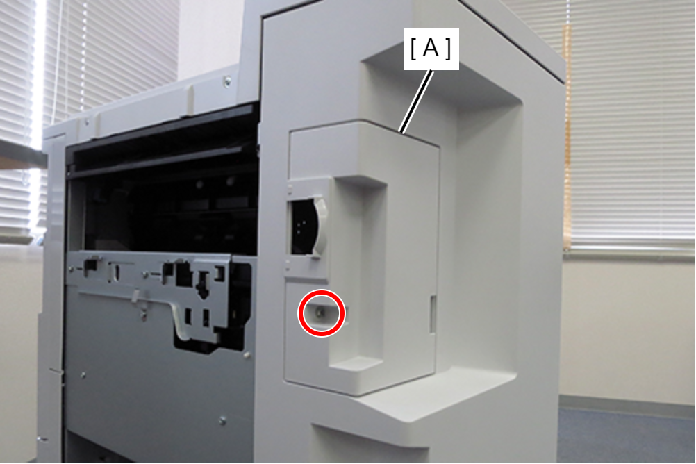
- Remove 1 screw and remove the rear cover sub (A).
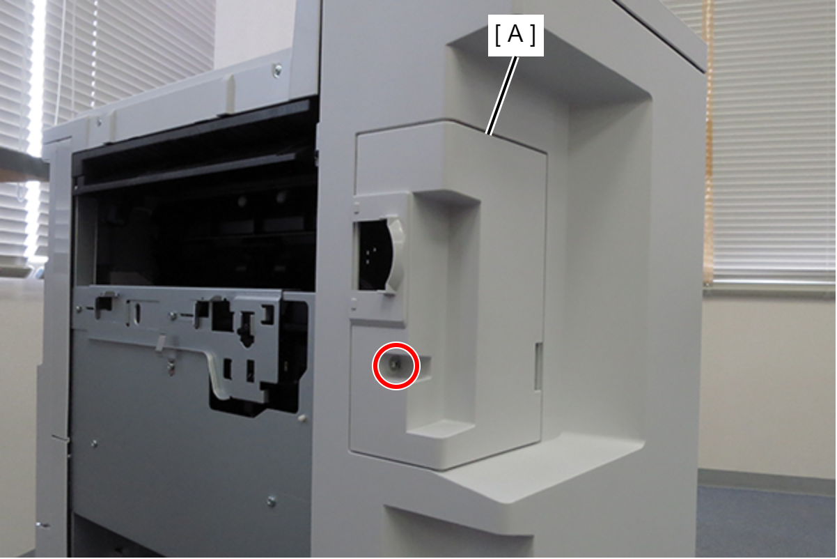
 : 4x10DC/P
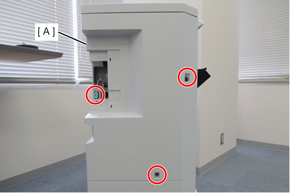
- Remove the 3 screws and remove the upper rear cover (A).
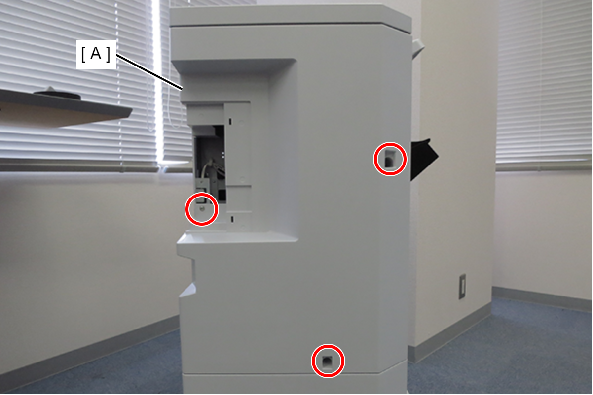
- : 4x10DC/P
- Remove 1 screw and remove the cover plate (A).
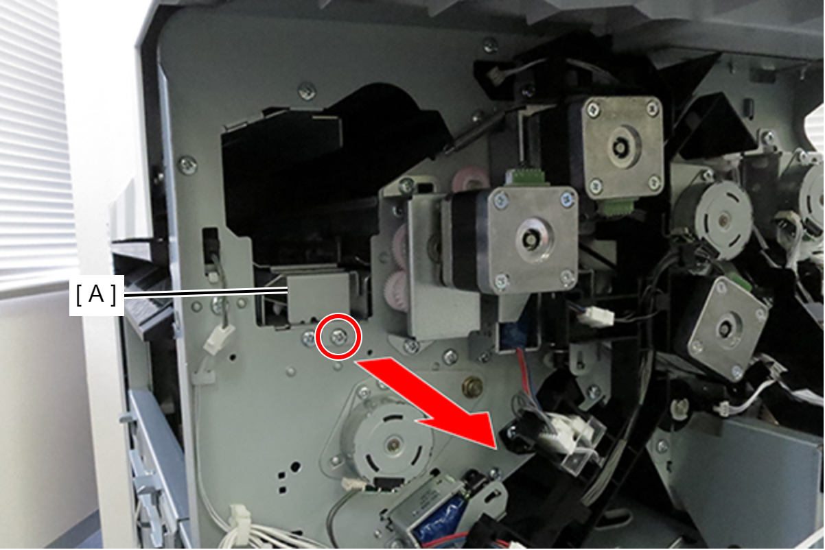
- : 3x8D/P
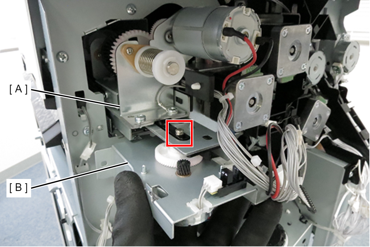
- Attach the punch guide (A) to the hole (B) in the frame.
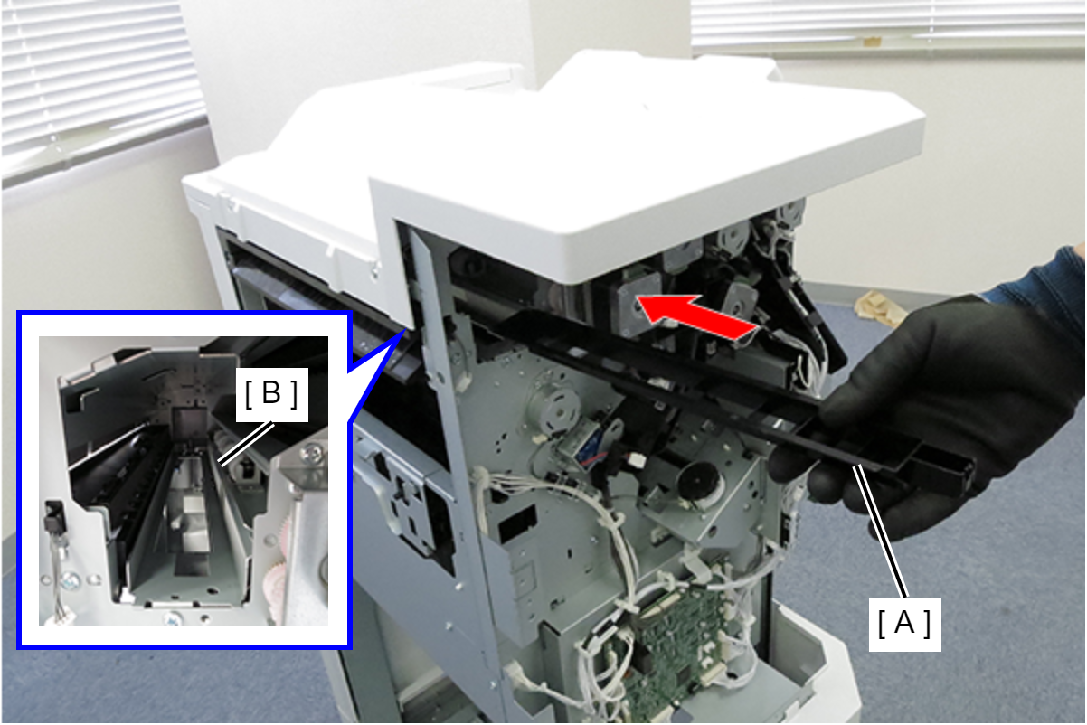
 Assembly / 組み立て
Install the punch guide by inserting the tab (A) at the tip of the punch guide under the frame.
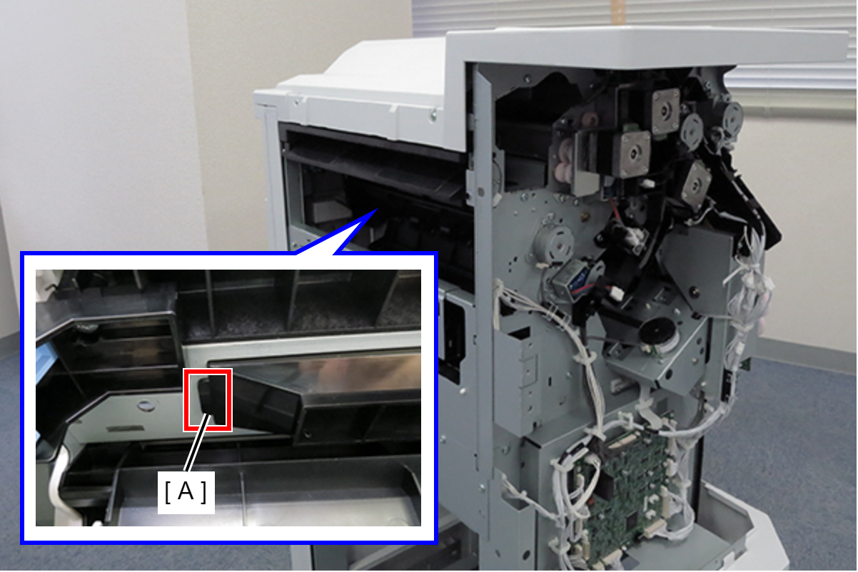
- Slightly lift the rear end of the punch unit (A) and insert it slowly.
 Caution / 注意
If you insert the punch unit with the rear end lowered, the parts on the bottom may be caught and damaged.
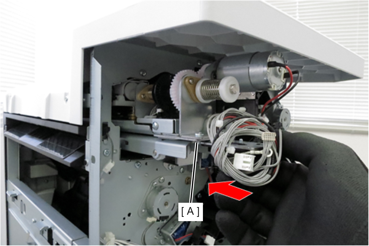
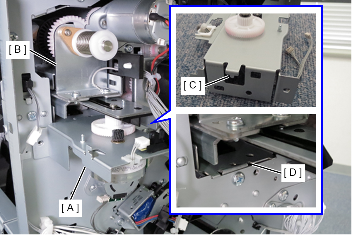
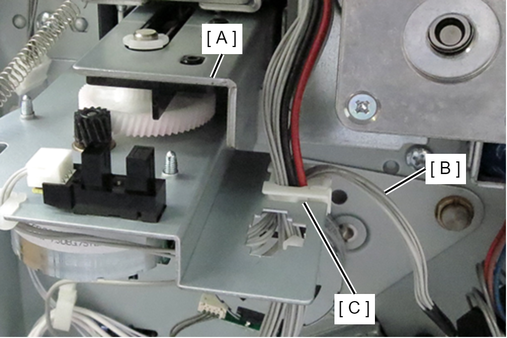
- Pull out the punch unit (A) slightly and insert the shaft of the motor unit (B) into the hole in the punch unit (A).
- Lift and insert the punch unit (B) together with the motor unit (A), lower it at the perforation position, and attach the hook (C) of the motor unit to the hole (D) of the frame.
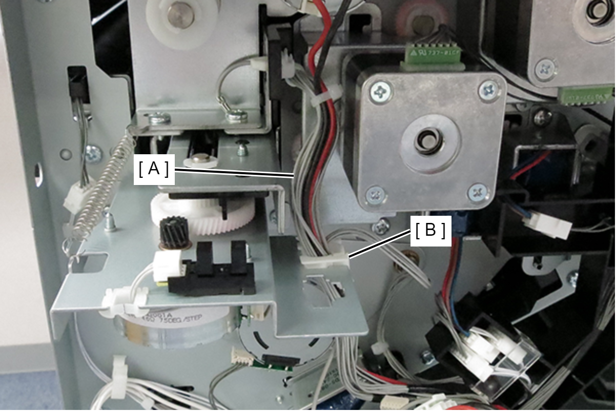
- Secure the motor unit (A) with 2 screws.
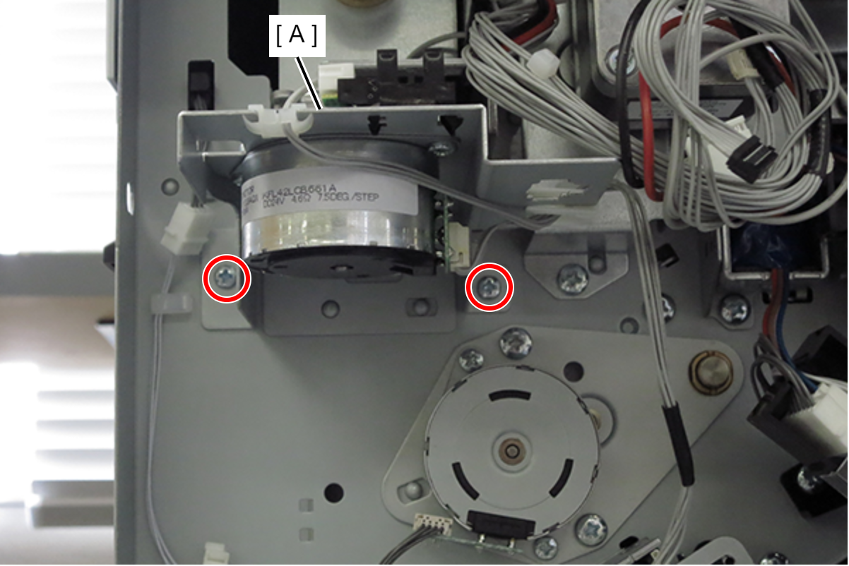
- : 3x8D/P
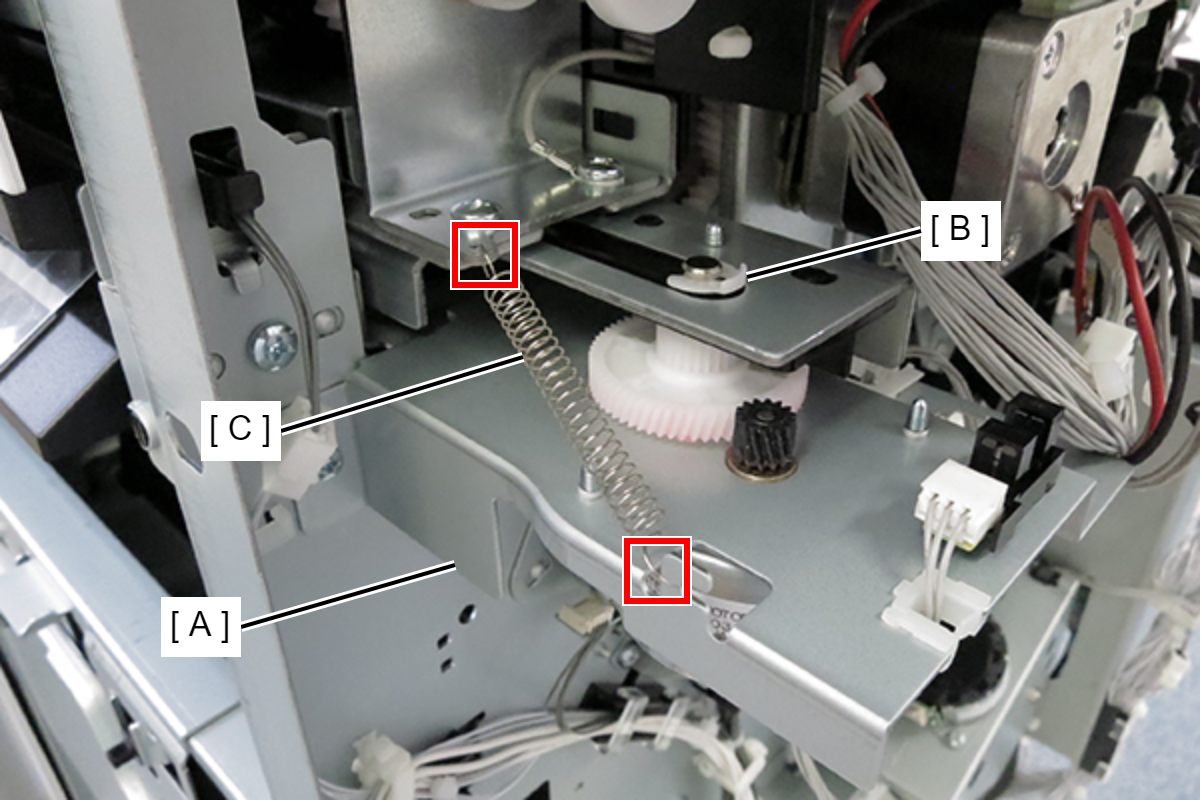
- Attach the stopper ring (B) to the shaft of the motor unit (A), and attach the spring (C) to the hooks of the punch unit and motor unit.
- Pass all cables (A) of the punch unit through the cable clamp (B) of the motor unit.
- Hang the 2 hooks (B) of the punched board (A) on the cutouts (C), insert the projections (E) into the holes (D) of the punched board, and attach the punched board.
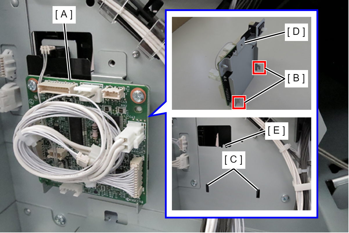
- Tighten the grounding wire (A) and the punch board (B) together with one screw.
- : 3x8D/P
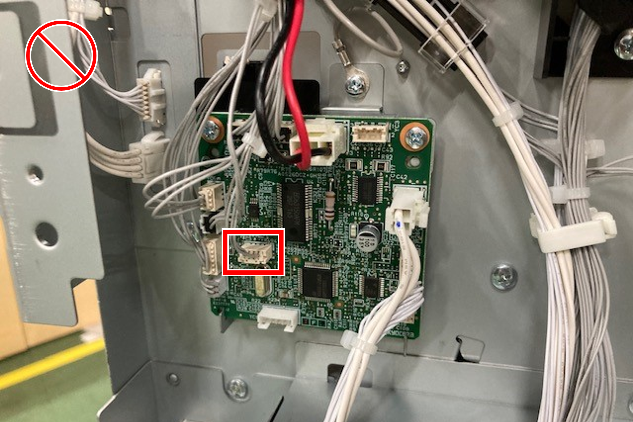
- Connect the 4 cables of the punch unit and motor unit to the connectors on the punch board (A).
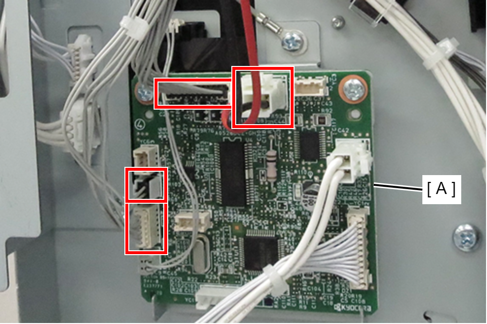
- Release the 2 cables (B) of the motor unit (A) from the cable clamp (C).
- Connect the 2 cables of the motor unit to the connectors on the punch board (A).
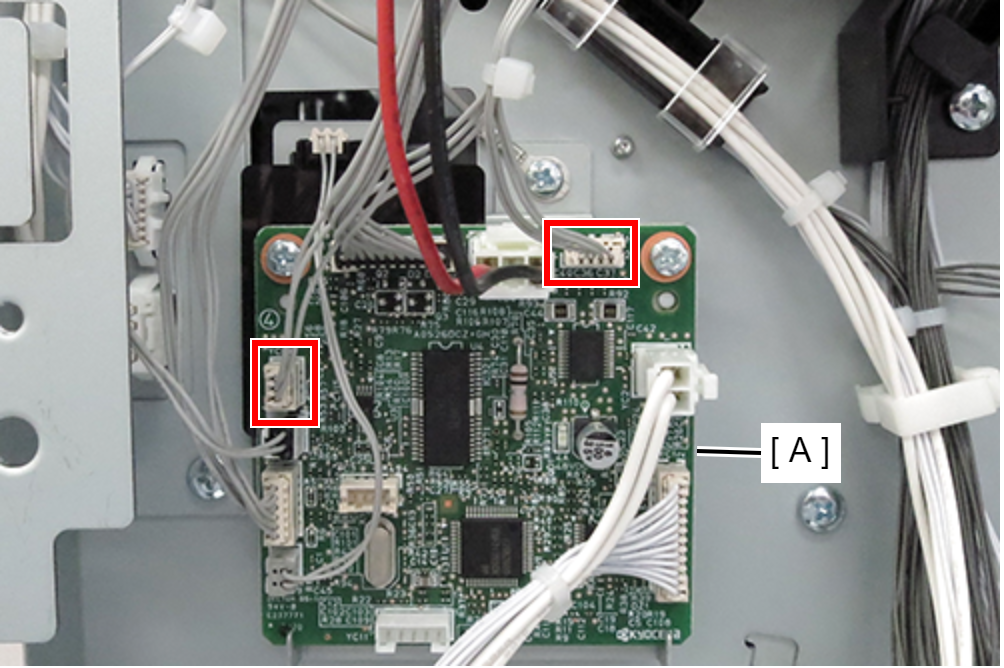 Caution / 注意
Be careful not to make a mistake the cable of the motor unit.
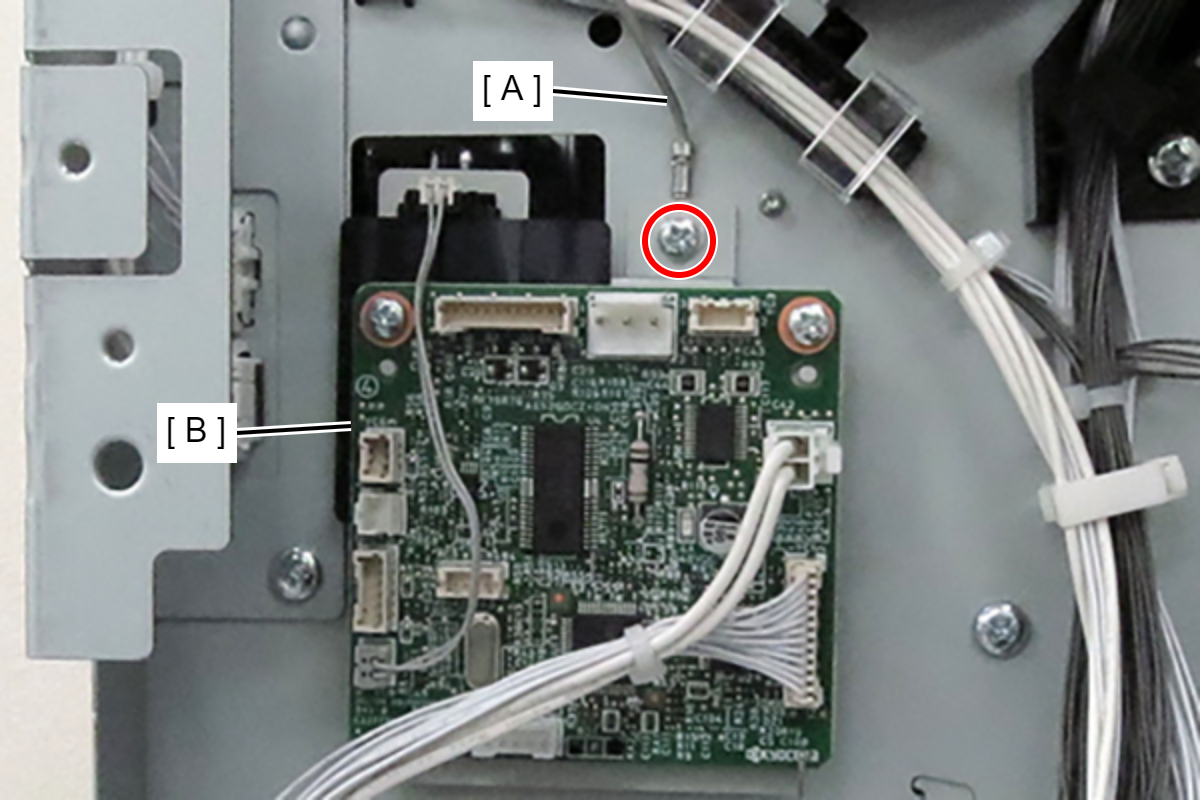
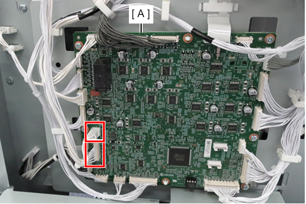
- Connect the 2 punch board cables to the finisher main board (A) connectors.
- Attach the clamp (A) and route the cable (B) of the motor unit and punch unit.
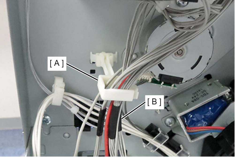
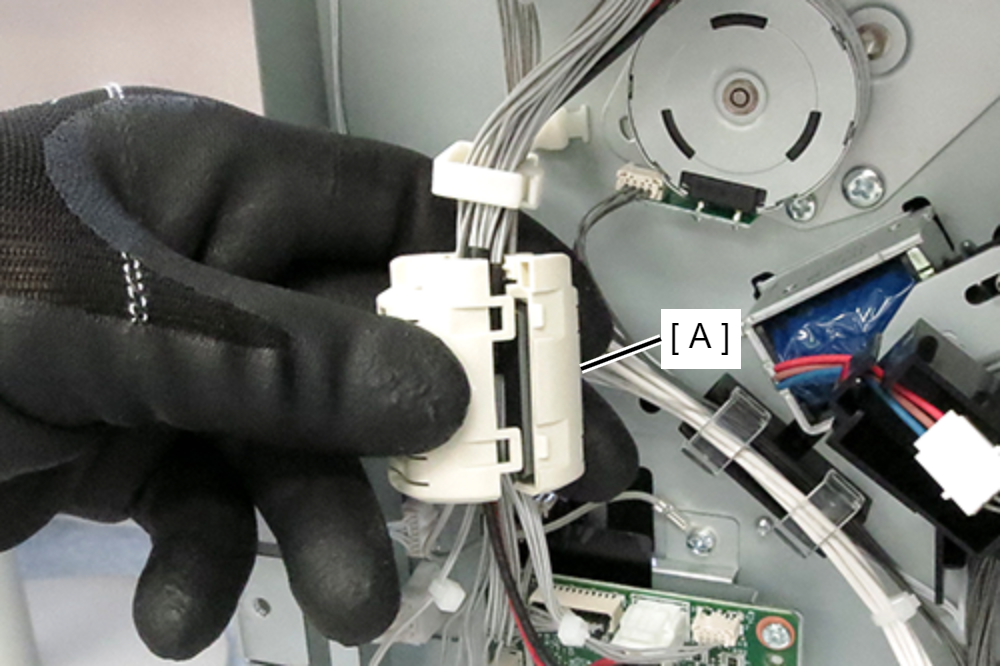
- Attach the ferrite core (A) to the position shown in the diagram.
- Attach the upper rear cover (A) and secure it with 3 screws.
- : 4x10DC/P
- Install the rear cover sub (A) and secure it with 1 screw.
- : 4x10DC/P
- Open the front cover (A) and insert the punch scrap box (B).
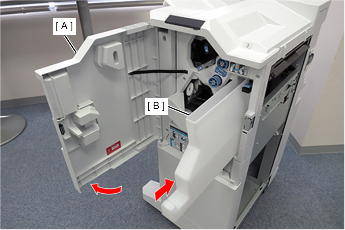
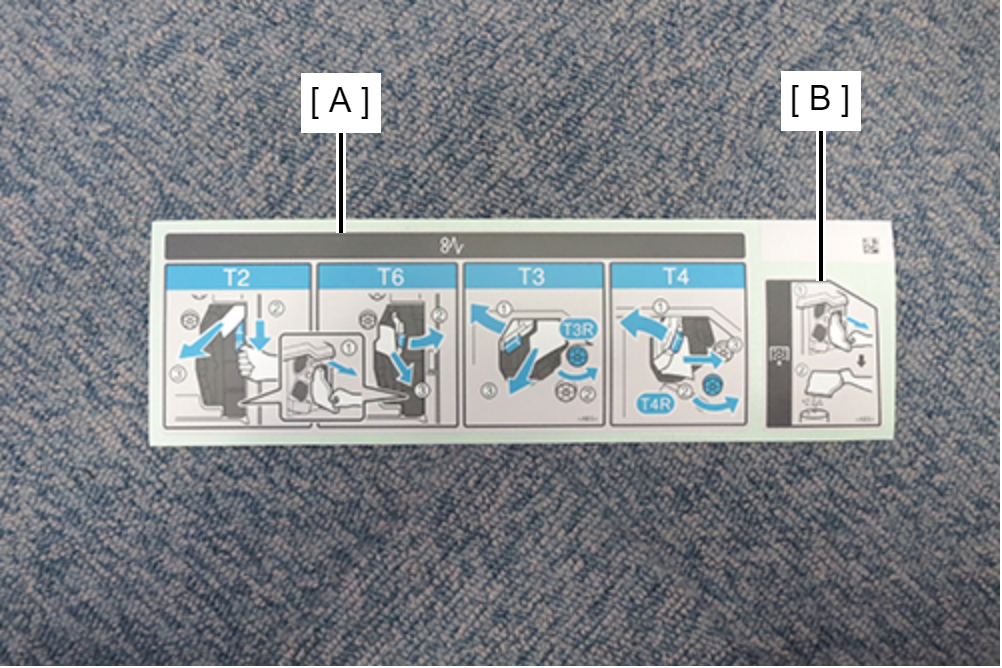
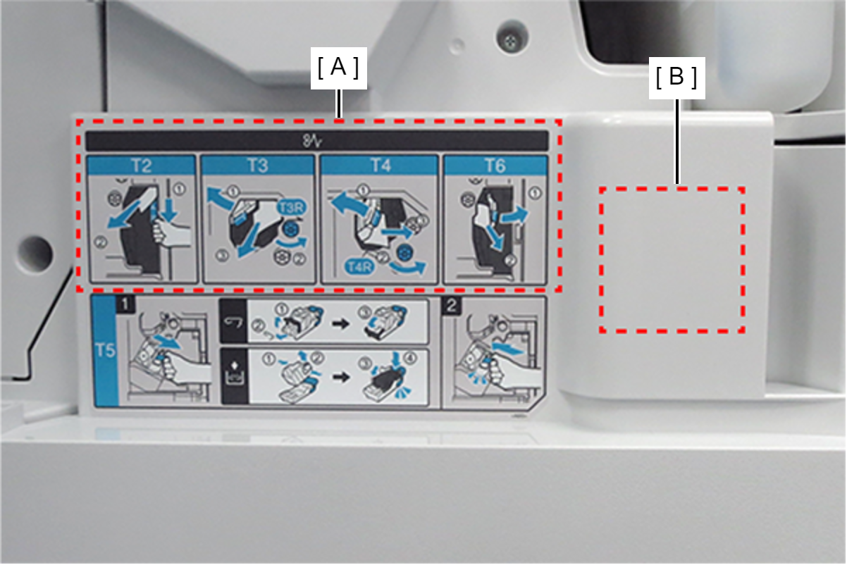
- Paste the included labels (A) and (B) of the Bundled Items to the locations shown in the illustration, and close the front cover.