Inner Punch Unit Initial Adjustment Procedure
Punch Unit Enable Setting
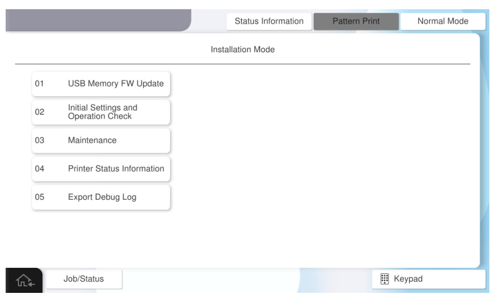
- Start the installation mode.

- Select [02 Installation Setting / Operation Check].
- Select the [Inner Finisher] tab.
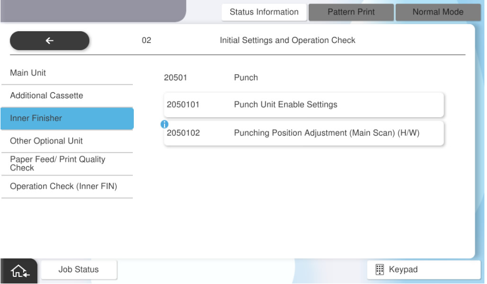
- Select [Punch Unit Enable Settings].
- Select [Status].
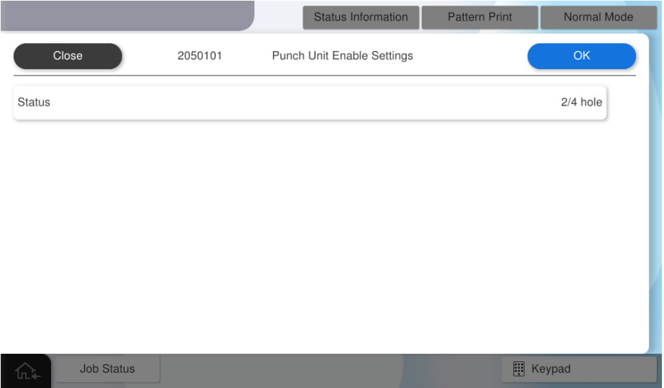
Select the status to be used.
 Check Point / チェックポイント
- Select an item according to the purpose of the attached punch unit.
- If the wrong destination is selected, the punching process cannot be performed correctly.
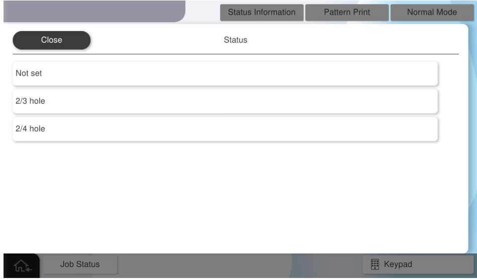
- Press [OK].Check Point / チェックポイント
After activating the inner punch unit, restart the main unit.
Punching Position Adjustment (Main Scan) (H/W)
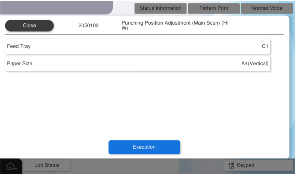
- Select [Punching Position Adjustment Main Scan Direction (Hardware)].
- Select [Paper Tray].

- Select the paper tray to use.
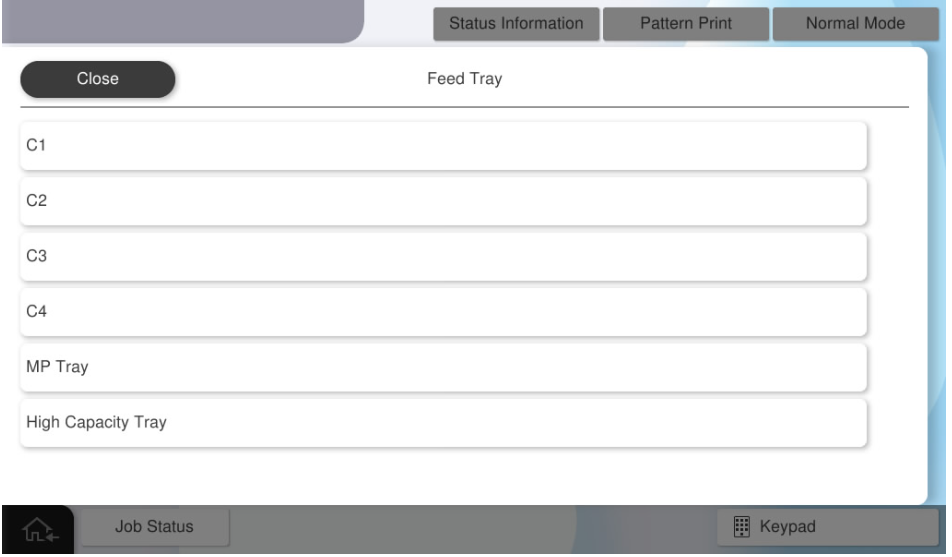
- Select [Paper Size].

- Select the paper size to use.

- Press [Execution].
- Fold the adjustment pattern so that the printed side of the adjustment pattern faces inside.
- Marking is performed on the offset positions of the overlapping holes of the adjustment pattern. If the holes are not misaligned, no adjustment is necessary.
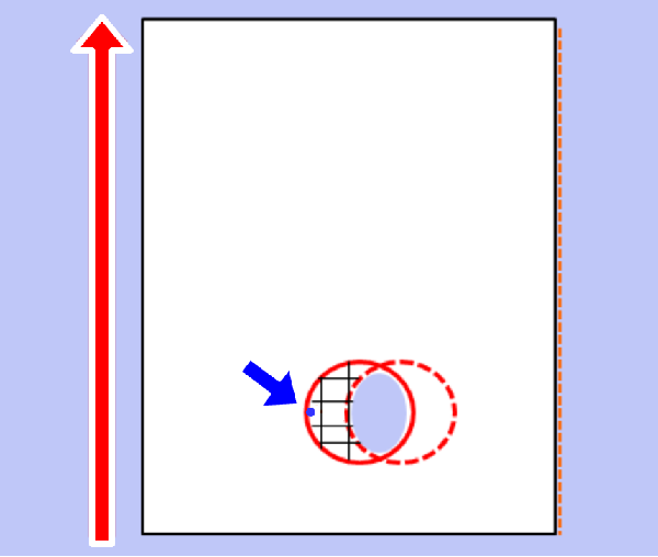
- Open the alignment pattern and measure the distance (#3) between the marking and the hole outline.
Convert the measurement result (#3) to an adjustment value.
Check Point / チェックポイント- Adjustment value calculation method: Adjustment value = measurement result ÷ 2
Example) When the measurement result is 3 mm Adjustment value = 1.5mm
- Adjustment value calculation method: Adjustment value = measurement result ÷ 2
- Change the mounting position of the inner punch unit.
- Pull out the inner finisher.
- Remove one screw and remove the front cover of the inner punch unit (A). (S7:
 )
)
- S7: C.B.STITE(P4), SCREW, 3X10, F/ZN3C
- Loosen the fixing screw (A) of the inner punch unit, and change the attachment position of the inner punch unit based on the adjustment value calculated in step 10.
 Check Point / チェックポイント
Check the parking position written on the adjustment pattern again and decide the direction to move the unit.
- When the marking is written on the right side of the punched hole (+ side)
 Move to the front side of the product.
 - When the marking is written on the right side of the punched hole (- side)Move to the back side of the product.
When moving the inner punch unit, refer to the frame memory (1 memory = 1 mm).
- When the marking is written on the right side of the punched hole (+ side)
- Tighten the fixing screw (A) of the inner punch unit, and put the inner finisher back.
- Output the adjustment pattern again, and if the misalignment of the holes is improved, press [Close] to finish the adjustment and assemble the front cover of the inner punch unit.
If you need to continue adjusting, repeat the adjustment from step 16. - Press [OK] to complete the setting.
Operation Check
When installing the inner punch unit, check the following operations.
- Staple Stack (Rear 1 position)
- Staple Stack (Front 1 position)
- Staple Stack (2 positions)
- Shift Stack
- Straight Stack
- Punch Stack (2 holes)
- Punch Stack (Others)
- Start the installation mode.
- Select [02 Installation Setting / Operation Check].
- Select the [Inner Finisher Operation Check] tab.
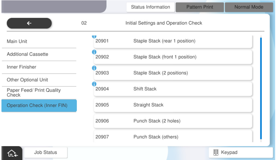
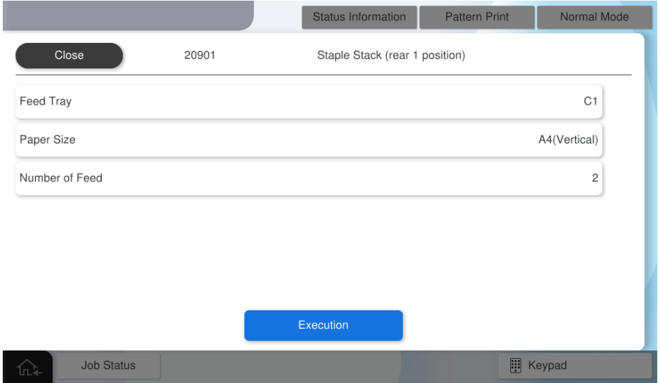
- Select [Staple Stack (rear 1 position)].
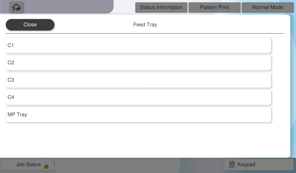
- Select [Paper Tray].
- Select the paper tray to use.
- Select [Paper Size].
- Select the paper size to use.
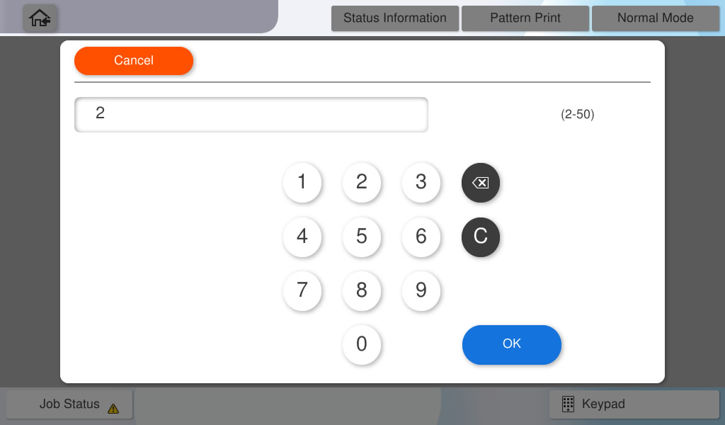
- Select [Number of Feed].
- Input the number of sheets to feed and press [OK].
Press [Execute] and check the operation result.
 Note / 補足 Note / 補足 |
Follow the same procedure to confirm the following operations, and confirm that they work correctly.
|