Inner Tray Installation Procedure
Bundled Items
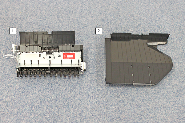
| No. | Bundled Item | Qty |
|---|---|---|
| 1 | Floor Bridge Unit B | 1 |
| 2 | Inner Tray | 1 |
| - | Stacker Support | 1 |
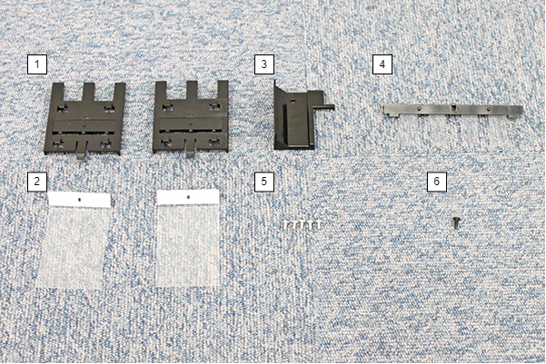
| No. | Bundled Item | Qty |
|---|---|---|
| 1 | Sheet holder | 2 |
| 2 | Paper holding sheet | 2 |
| 3 | Blindfold Covers | 1 |
| 4 | Blindfold sheet Assy | 1 |
| 5 | Screw M3 × 6 | 5 |
| 6 | Screw M3 × 8 | 1 |
Installation Procedure
Items to Prepare
- Gloves
- Cutter
- Phillips (+) screwdriver
Minimum number of workers
1 person
 Caution / 注意 Caution / 注意 |
Be sure to check the following precautions before installation.
|
Installation Procedure
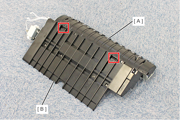
- Release the two hooks on floor bridge unit B (A), slide the cover (B), and remove it.
- Install the blind sheet assembly (B) to the floor bridge unit B (A).
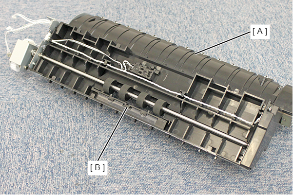
- Install the cover removed in step 1.
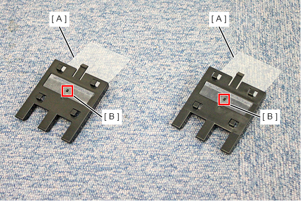
- Peel off the release paper of the paper holding sheet (A), align the positioning holes with the dowels (B) of the sheet holder, and attach it.
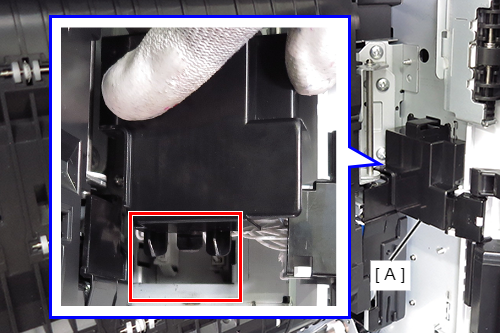
- Remove one screw and remove the FD paper guide (A).
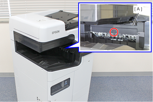
 :3x8D/BK/P
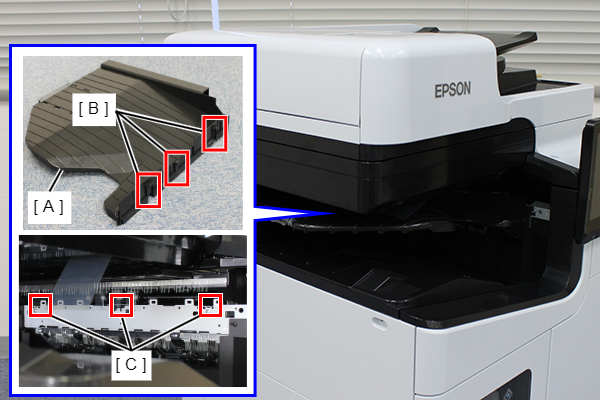
- Attach the seat holder (C) by aligning the 4 hooks (B) of the seat holder with the 4 holes (A) on the bottom of the SCN unit, and slide it in the direction of the arrow to fix it.
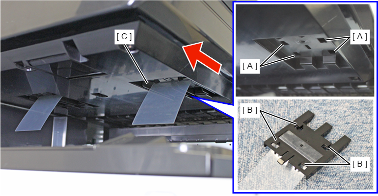
- Install another Sheet holder in the same way.
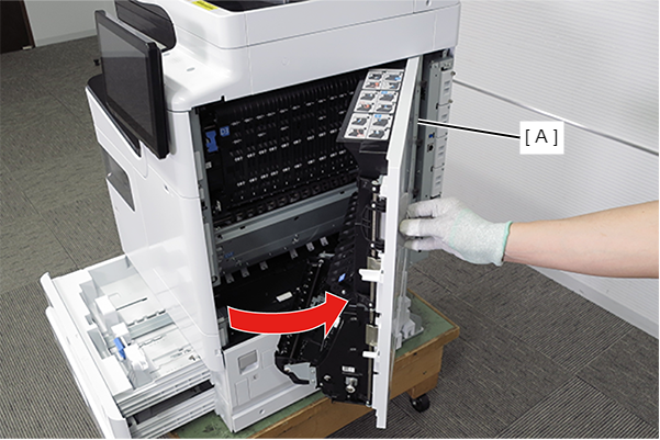
- Pull the lever to open the Right Door Unit (A).
- Remove the Right Door Cable Cover while releasing the hook.
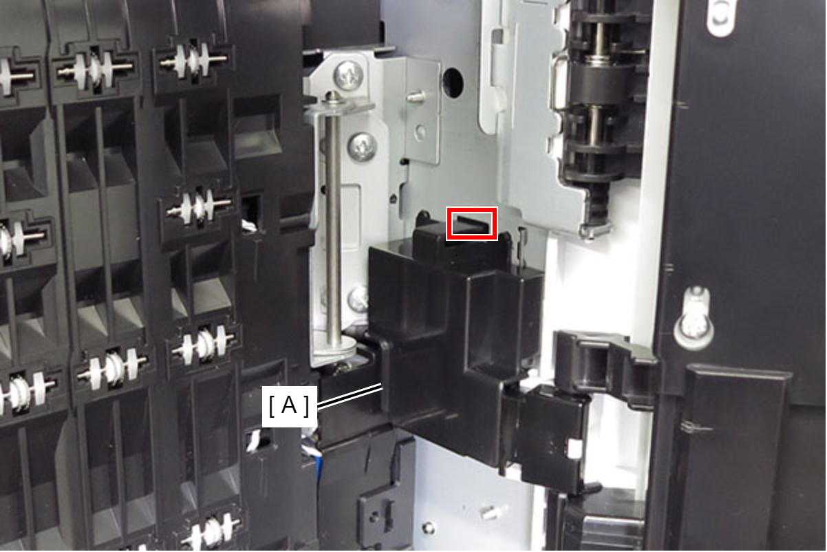
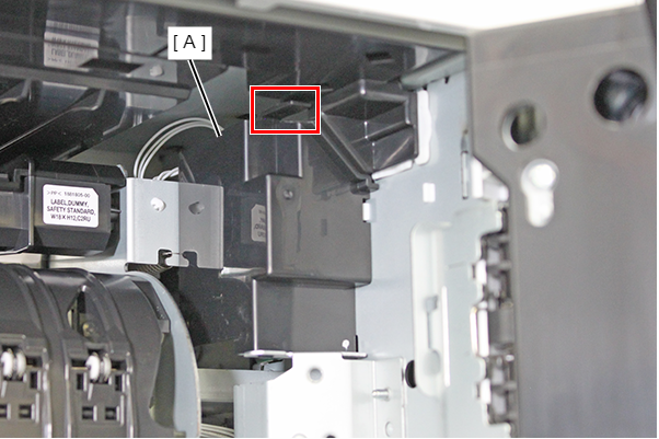
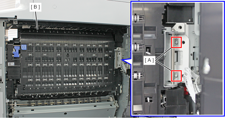
- Slide the D3 connector cover (A) in the direction of the arrow to release the 2 hooks and remove the connector cover.
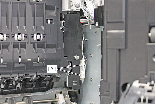
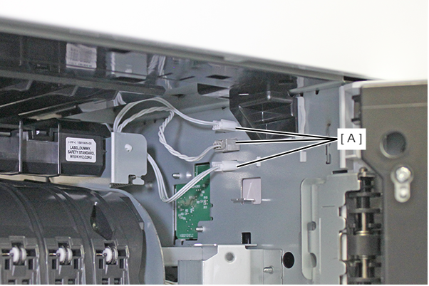
Disconnect the cables from the 2 connectors (A).
 Note / 補足
- Cable colors are as follows.
- Upper side: black
- Lower side: white
- Cable colors are as follows.
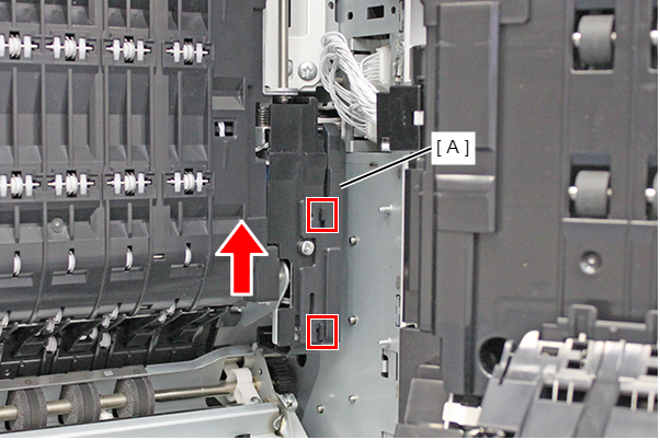
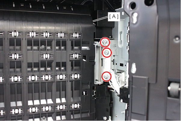
- Remove 3 screws and pull the lever (A) to remove the D3 Unit (A).
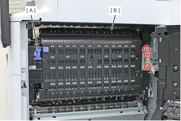
- : 4x8D/P
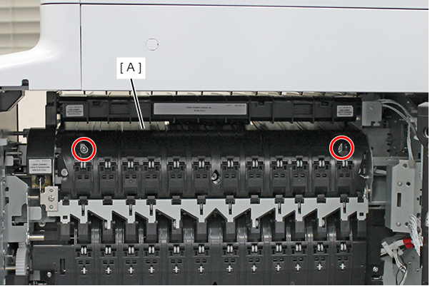
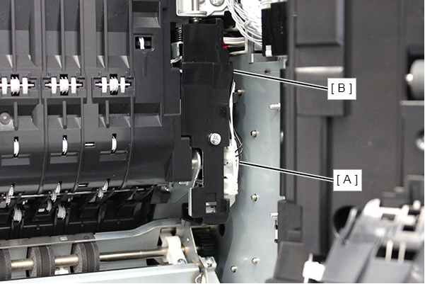
- Remove the 2 screws and remove the pre-ejection paper guide (A).
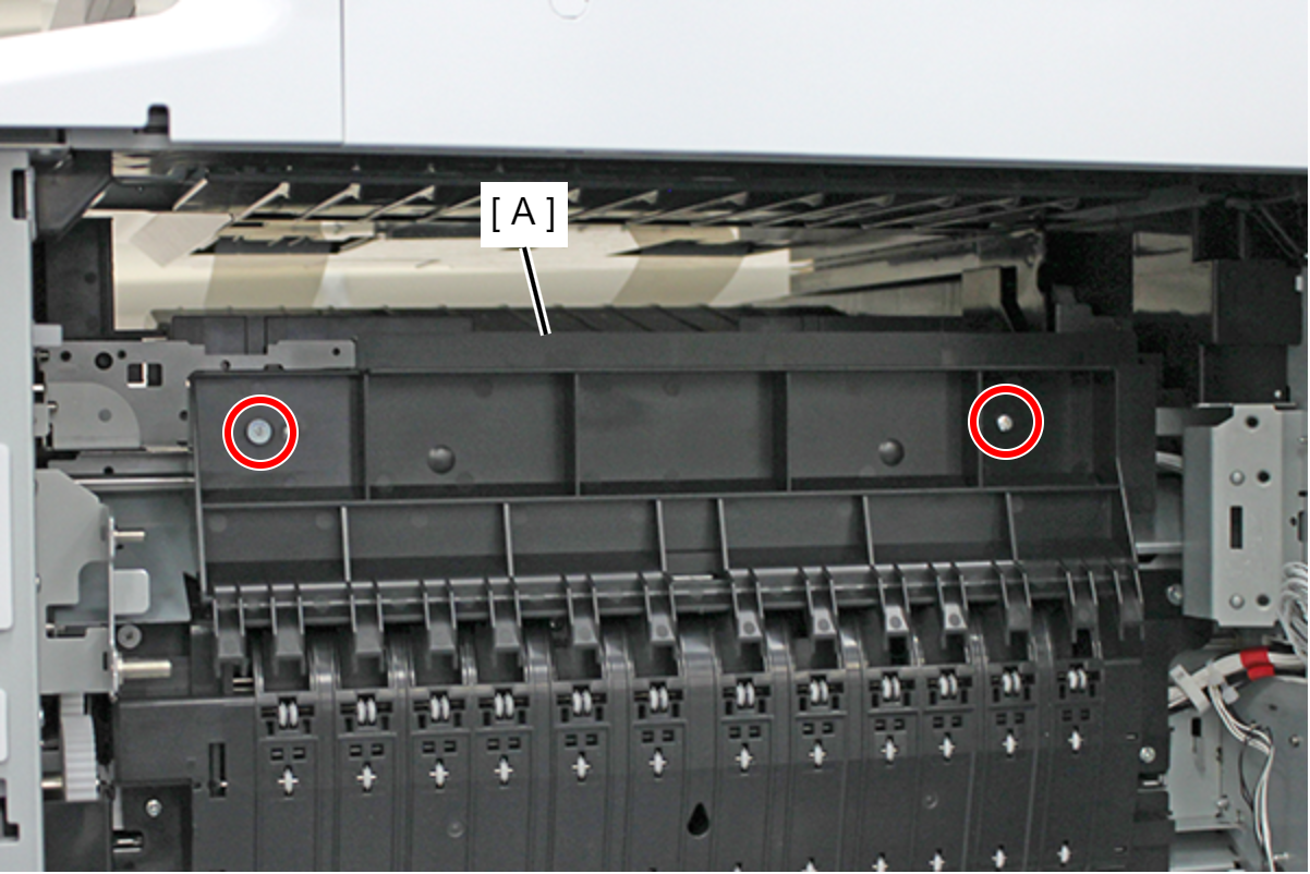
- : 3x5D/TBD
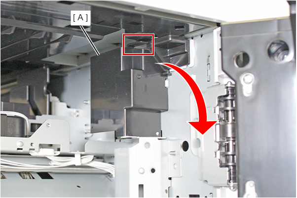
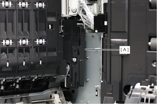
- Remove the FD cable cover (A) by rotating it in the direction of the arrow while releasing the hook.
- Insert the tab (B) marked with a line into the hole (A) of floor bridge unit B, and attach floor bridge unit B (C).
- Check that the frame of floor bridge unit B protrudes from the 3 holes (A) on the paper output side, and tighten the 3 screws.
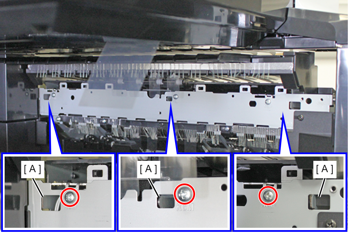
- : 3x6D/P
- Tighten the 2 screws to secure Floor Bridge Unit B (A).
- : 3x8D/P
- Connect the 3 cables of floor bridge unit B to the 3 connectors (A).
Align the two dowels (A) with the two holes (B) and attach the FD cable cover (C).

 Assembly / 組み立て
Make sure that the hook of the FD cable cover (A) is engaged.
- Align the hinge dowels with the two positioning holes (A), close the lever side, and attach the D3 unit (B).
- Tighten the 3 screws to secure D3 Unit (A).
- : 4x8D/P
- Connect the 2 cables (A) to the connectors on the D3 unit and place them inside the hook (B).
 Caution / 注意
Be careful not to confuse the connection destination of the cable.
- Attach the D3 connector cover (A).
- Insert the tab into the frame and attach the right door cable cover (A).
- Close the Right Door Unit.
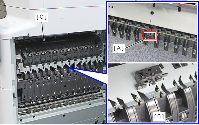
- Hook the 3 hooks (B) of the Inner tray (A) to the 3 notches (C) of the frame, and attach the Inner tray.
- Install the blind cover (A) and secure it with one screw.
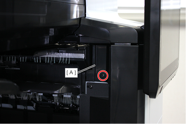
- : 3x8D/BK/P
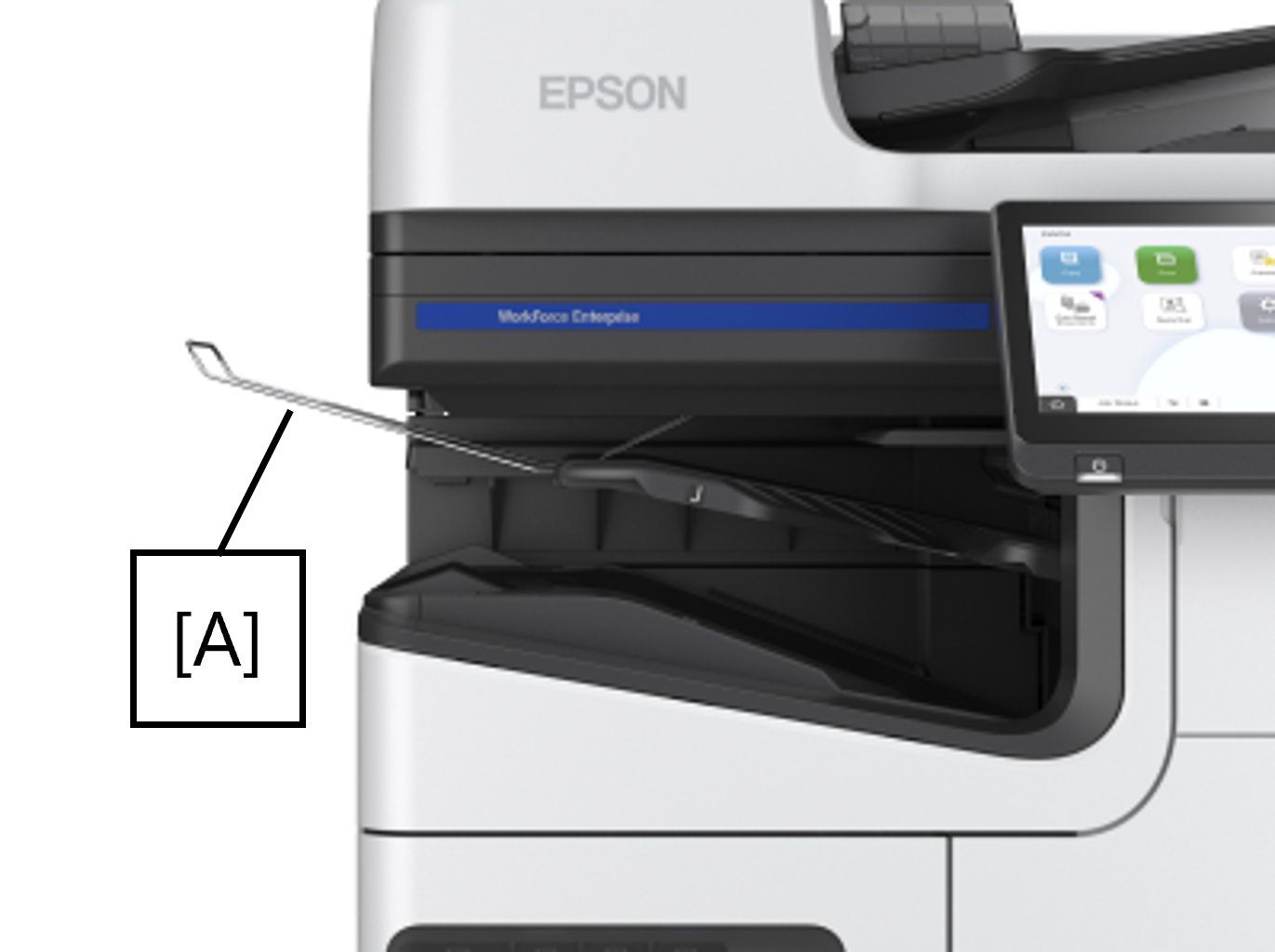
- Set the stacker support on the inner tray.