Saddle Unit Installation Procedure
 Caution / 注意 Caution / 注意 |
|

Items to Prepare
- Saddle Unit included items
- Phillips (+) screwdriver
- Stubby driver
Installation Procedure
- Remove the screws that secure the front caster cover (A) and the rear caster cover (B).

 : 4x10DC/P
Remove the 2 screws, spread the front caster cover (A) and rear caster cover (B) outward, and remove the lower left side cover (C).

 : 4x10DC/P
 Note / 補足
Dispose of the removed screws and under the left cover in accordance with the local regulations of the installation site.
- Attach the 2 tray stopper plates (A) and secure them with 1 screw each.
- (Rear side)

- : 4x8D
- Front side

- : 4x8D
- (Rear side)
- Align the 2 protrusions (A) on the front rail with the 2 holes (B) on the frame, hook the hooks (C) to the notches (D), and attach the front rail.

- Secure the front rail (A) with 2 screws.

- : 4x12D/P
Align the 2 protrusions (A) on the rear rail with the 2 holes (B) on the frame, hook the hooks (C) to the notches (D), and attach the rear rail.

- Secure the rear rail (A) with 2 screws.

- : 4x12D/P
Place the 3 rollers (B) on the front and back sides of the saddle stitching unit (A) on the front and rear rails (C), and push them all the way in.
Caution / 注意The saddle unit weighs about 20 kg, so be careful not to overturn or drop it.
When placing the saddle unit on the rail, be careful not to hit the side of the saddle unit against the floor finisher and damage it.
 Check Point / チェックポイント
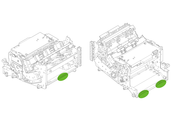
Hold on the positions shown in the figure when lifting the saddle unit.
(Carry-in side)

Pull out the saddle unit (B) while raising the lever (A).
(Paper ejection side)
- Align the 2 dowels on the front tray holder with the 2 holes on the floor finisher (A), and secure the front tray holder (B) with 4 screws.
(Paper ejection front side)
- : 3x8DC/P
- Pass the cable of the saddle tray unit (A) through the hole in the rear tray holder (B) and secure it with the clamp (C).

- Insert the ring part (A) of the saddle tray unit into the hole (B) of the rear tray holder to hold it temporarily.

- Insert the hole (B) of the front tray holder into the ring (A) of the saddle tray unit.
(Paper ejection front side)
- Align the 2 dowels on the rear tray holder with the 2 holes on the floor finisher (A), and secure the rear tray holder (B) with 4 screws.
(Paper ejection rear side)
- : 3x8DC/P
- Connect the cable of the saddle tray unit to the connector (A) and secure the ground wire (B) with 1 screw.
(Paper ejection rear side)
- : 3x8D/P
- Pull the lever to raise the V2 cover (A).

- Raise the saddle unit (A).

Insert the rear side cover (A) straight in and attach it by hanging the 2 hooks (B) on the 2 receiving parts (C) of the frame.
(Paper ejection rear side)
 Check Point / チェックポイント
Since the corner (A) of the rear side cover interferes with the protrusion (B), attach it by passing it under the protrusion (B).

- Secure the rear side cover (A) with 1 screw.

- : 3x8DC/P
Install the front side cover (A) in the same way.
After installing, move the lever (B) up and down and check that the front of the side cover does not interfere with the operation of the lever.(Paper ejection front side)

- Secure the front side cover (A) with 1 screw.
- : 3x8DC/P
- Lower the saddle tray unit (A) and lower the V2 cover (B).
(Paper ejection side)
- Reuse the 2 screws removed in Step 2.

- : 4x10DC/P
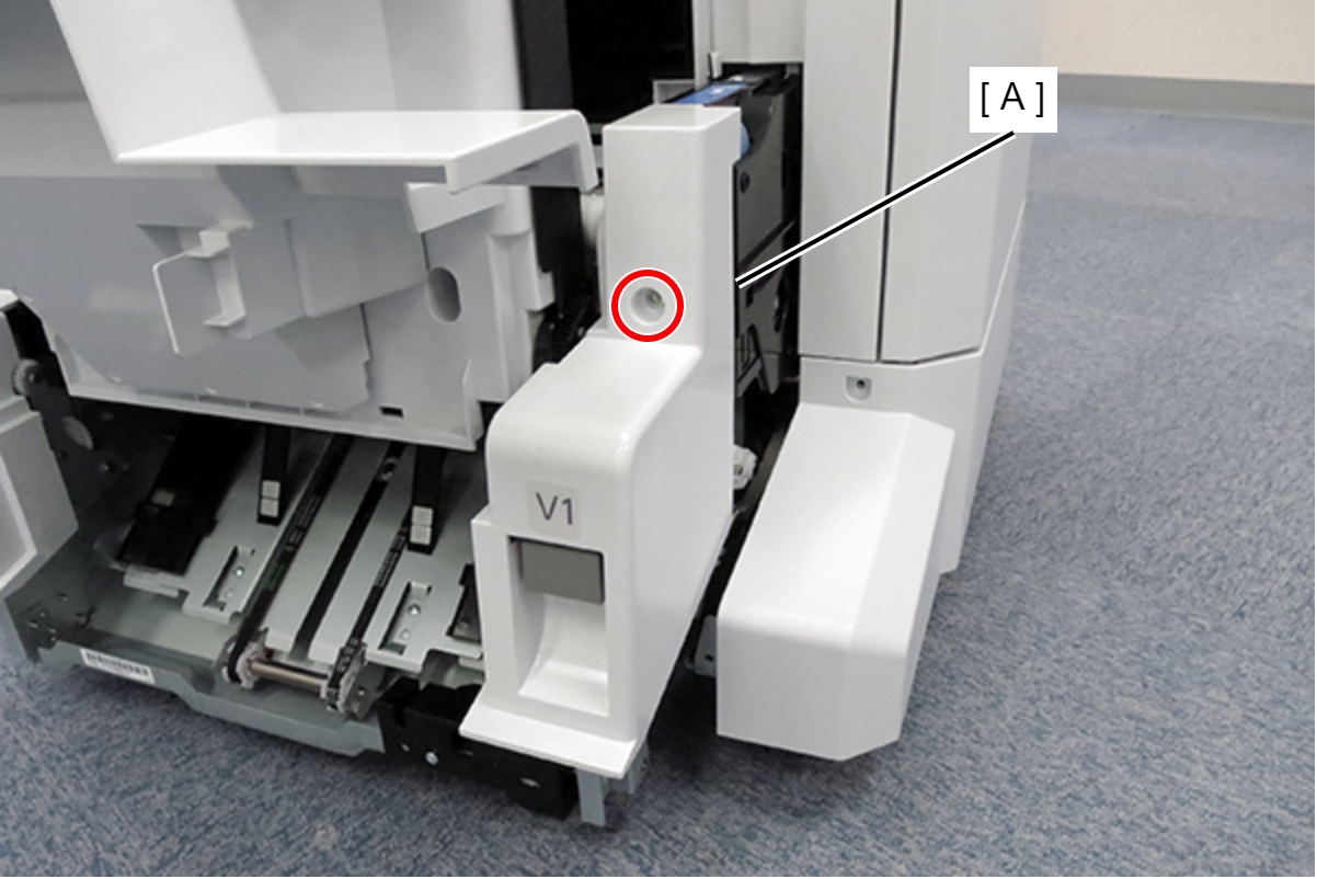
- Open the front cover (A), remove 1 screw, and open the lower front cover (B).
(Front side)
- : 4x10DC/P
Insert the saddle transport unit (B) through the jam release lever (A).
(Carry-in side)

- Pass the frame (A) on the front side of the saddle unit between the connector (B) and the mounting plate (C), and lift the saddle transport unit (D).

- Hook the 2 hooks (A) of the saddle transport unit to temporarily hold the saddle transport unit (B).

- Align the dowels with the 2 positioning holes (A), and secure the saddle transport unit (B) with 4 screws.

- : 4x8D
Remove the two tapes (B) from the cable holder (A).

- Sandwich the frame between the 2 projections (B) of the cable holder (A).

- Pass the cable holder screw (B) through the cable holder (A) and fix it by tightening the screw.
 Check Point / チェックポイント
The screw holes are not threaded and must be self-tapped by the cable holder screw (B).
Note that when self-tapping, the screw must be tightened vertically into the screw hole. If self-tapping is difficult, it is recommended to self-tap using the 4x8D screws used for fastening elsewhere (eg : step 29).Caution / 注意When tightening screws, there is a risk of contact with the internal parts or metal plate of the Saddle Unit.
Be careful not to injure yourself with the internal parts of the Saddle stitching or the sharp edges of metal plate.
- Secure the ground wire (A) with 1 screw and attach the cable tie (B).

- : 4x8D
Check Point / チェックポイント- Use a stubby driver to tighten the screws.
- Attach the cable ties with the band side facing the floor finisher as shown in the illustration.
- Bundle the cables with the cable tie (A), and insert the extra length of the cable tie into the gap between the cover and the frame.

- Connect the 4 cables to the 4 connectors.

- Install the reinforcement plate (A) and fix it with 4 screws.

- : 4x8D
- Push the saddle unit (A) all the way in.

Affix the instruction label (A) to the inside the front cover lower(B).
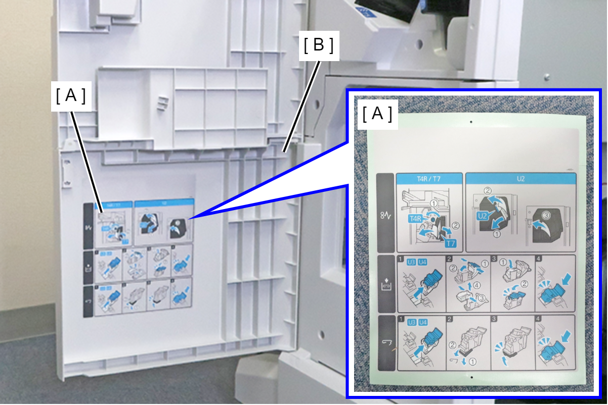
 Assembly / 組み立て
Before starting work, make sure that the attachment position is not dirty, and if it is dirty, clean it with a waste cloth.
Attach the T7 label (A) to the position shown.
 Assembly / 組み立て
Before starting work, make sure that the attachment position is not dirty, and if it is dirty, clean it with a waste cloth.
Attach the U1 label (A) to the position shown. (B: 4 mm)
 Assembly / 組み立て
Before starting work, make sure that the attachment position is not dirty, and if it is dirty, clean it with a waste cloth.
- Close the lower front cover (A) and front cover (B).
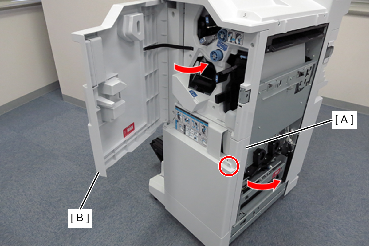 Check Point / チェックポイント
- When the saddle unit is installed, discard without tightening the screws at the front cover lower (A).
- Customers need to open and close the cover when saddle unit paper jam process.