Floor Finisher Installation Procedure
 Caution / 注意 Caution / 注意 |
Be sure to check the following precautions before installation.
|
 Check Point / チェックポイント Check Point / チェックポイント |
When using the saddle unit and floor punch unit, install the saddle unit and floor punch unit before installing the floor finisher. |
Items to Prepare
- Bundled Items of Floor Finisher
- Bundled Items of Floor Bridge Unit A
- Bundled Items of Floor Bridge Unit B
- Phillips (+) screwdriver
Installation Procedure
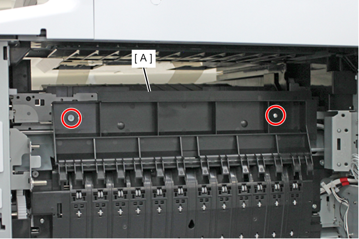
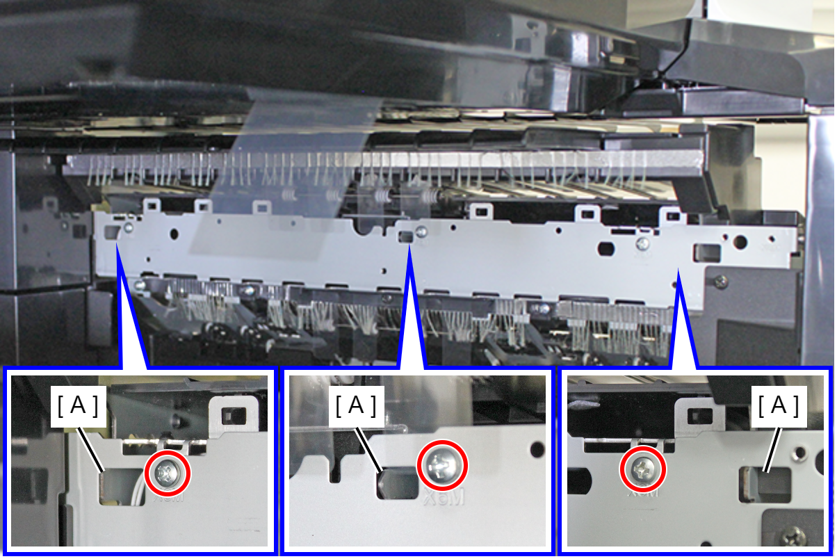
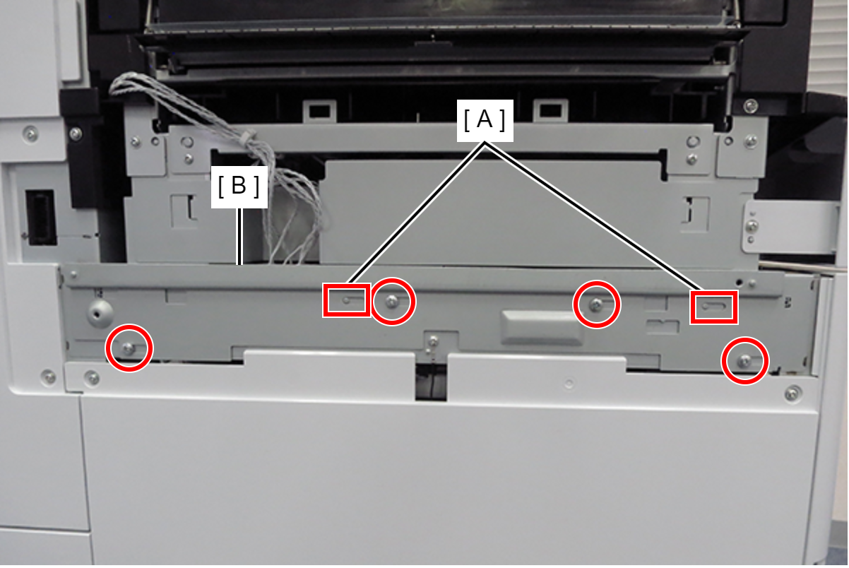
- Remove the 2 screws and remove the left cover upper (A).
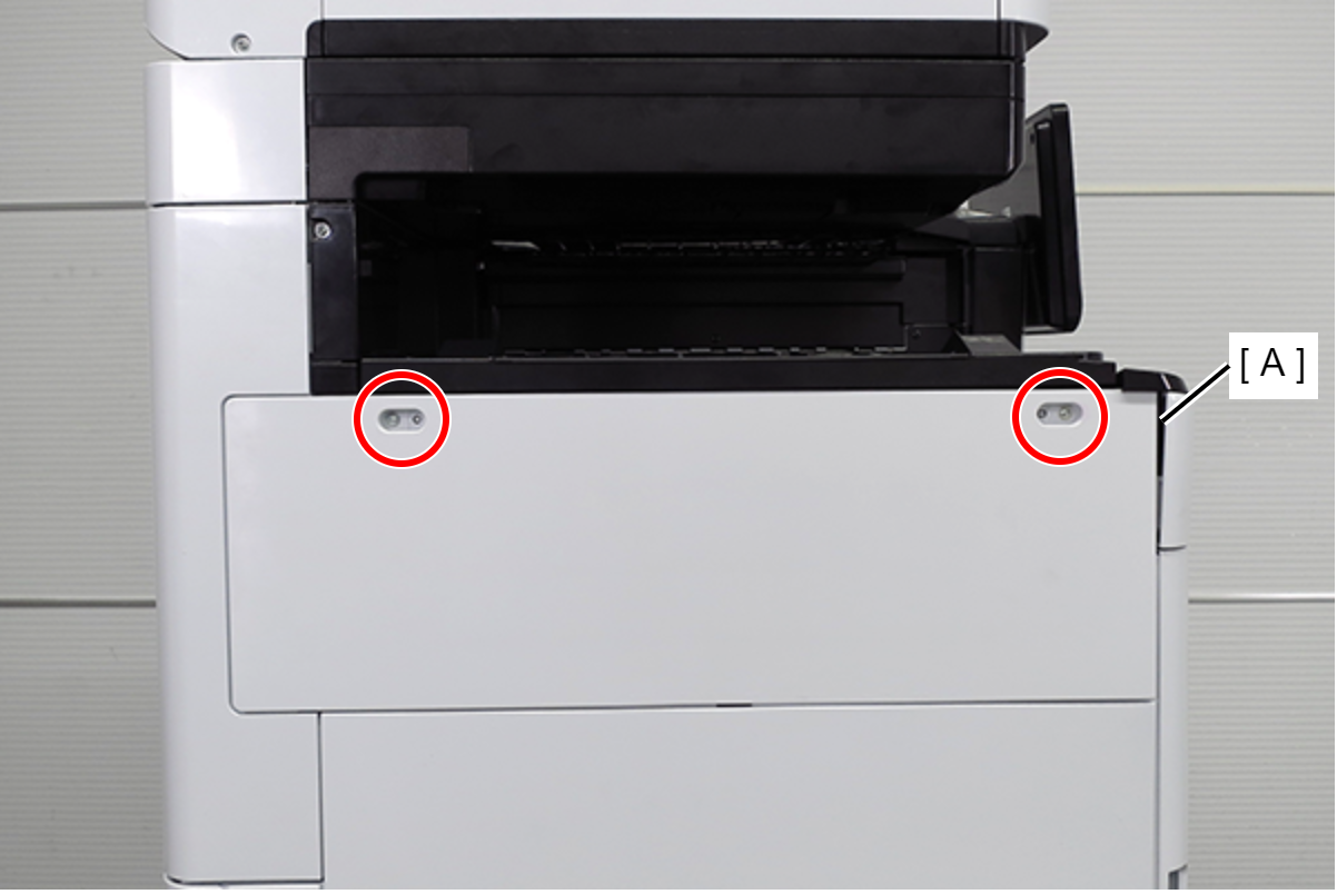
 : 3X10DC/P
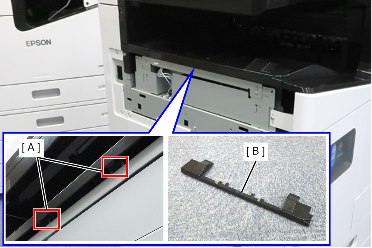
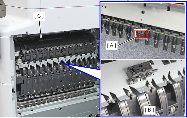
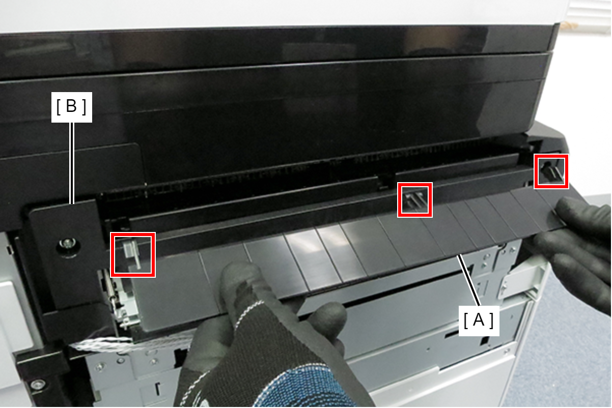
- Release the 2 hooks (A) and remove the FD stacker front end cover (B).
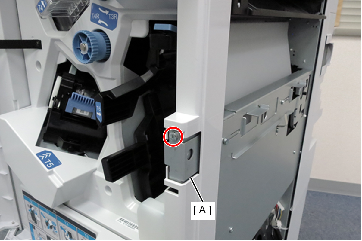
- Remove 1 screw and remove the FD Inner Cover Upper (A).

- : 3x8DW/P
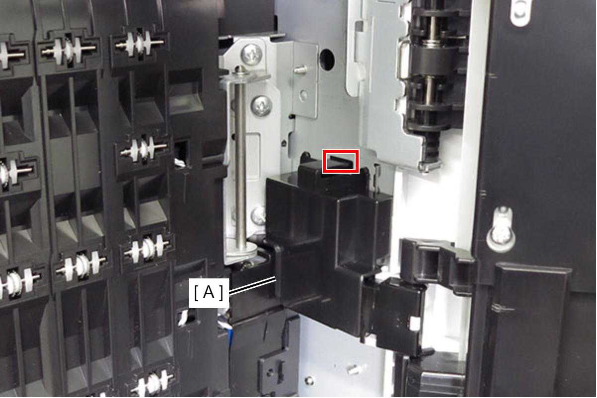
- Remove 1 screw and remove the FD paper guide (A).
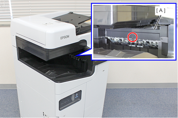
- : 3x8D/BK/P
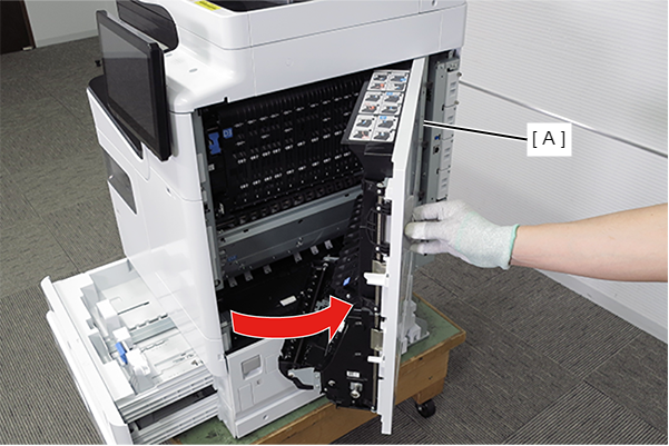
- Pull the lever to open the Right Door Unit (A).
- Remove the Right Door Cable Cover while releasing the hook.
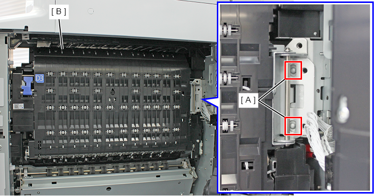
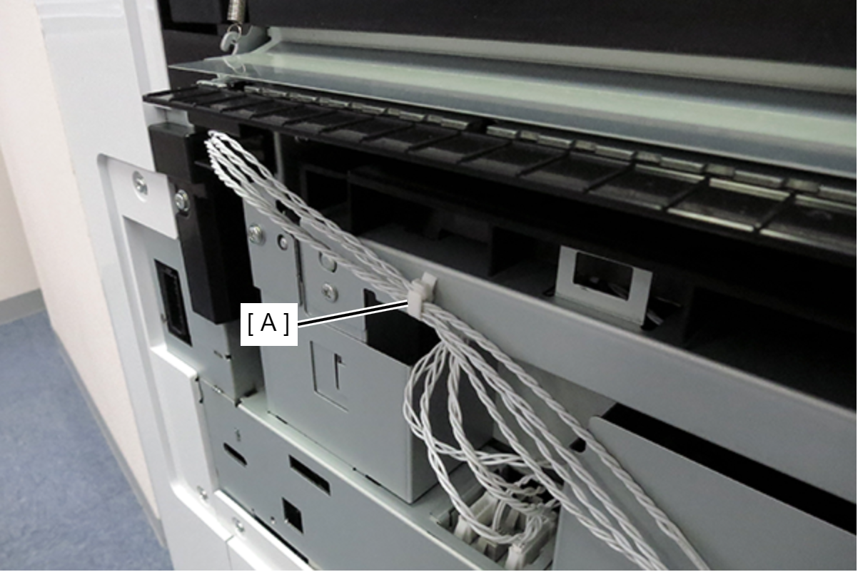
- Slide the D3 cable cover (A) in the direction of the arrow to release the 2 hooks and remove the D3 cable cover.
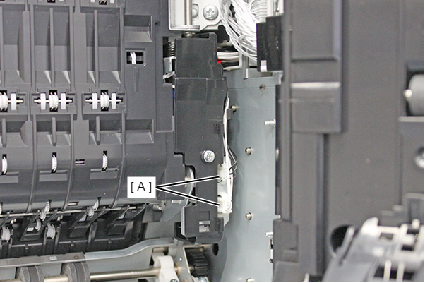
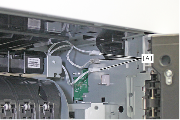
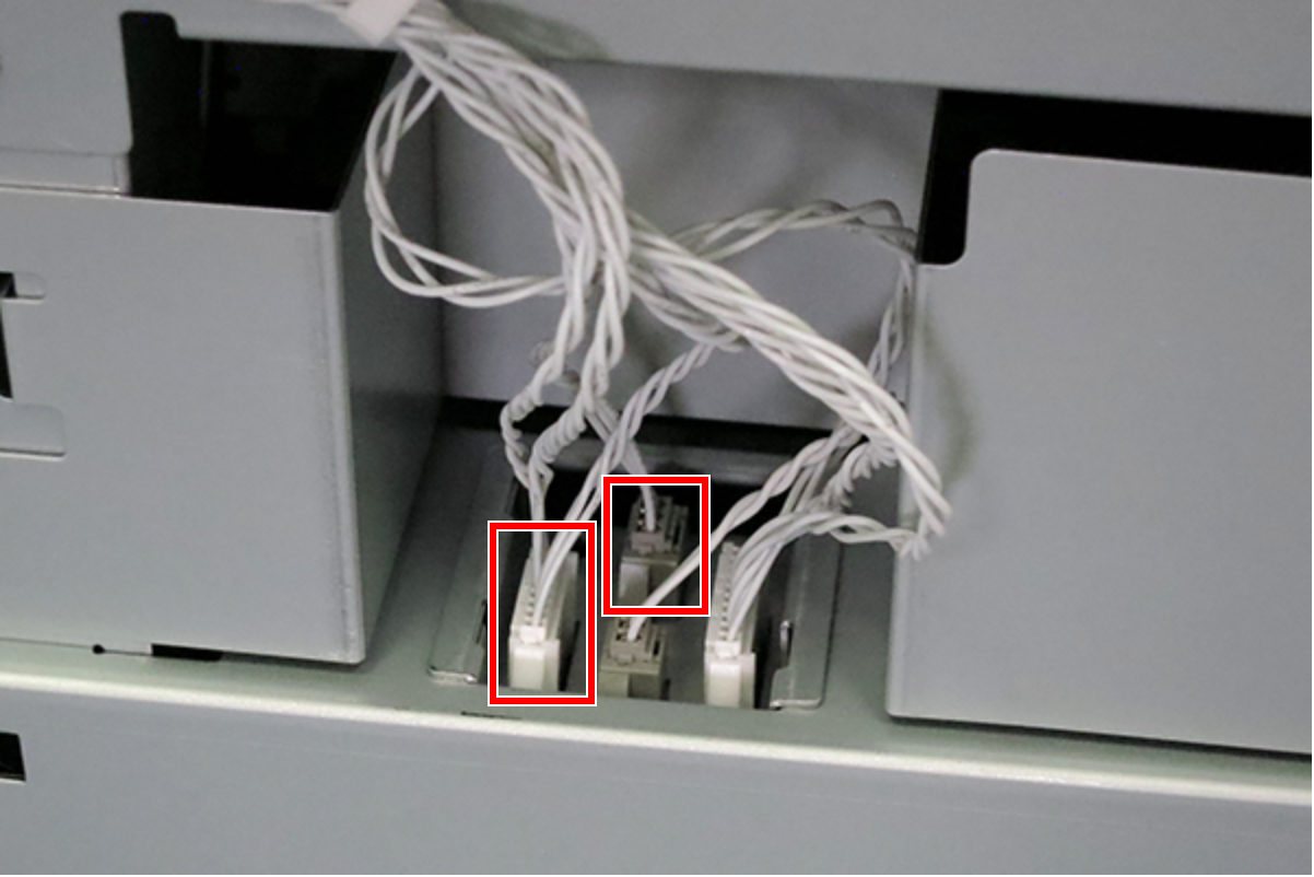
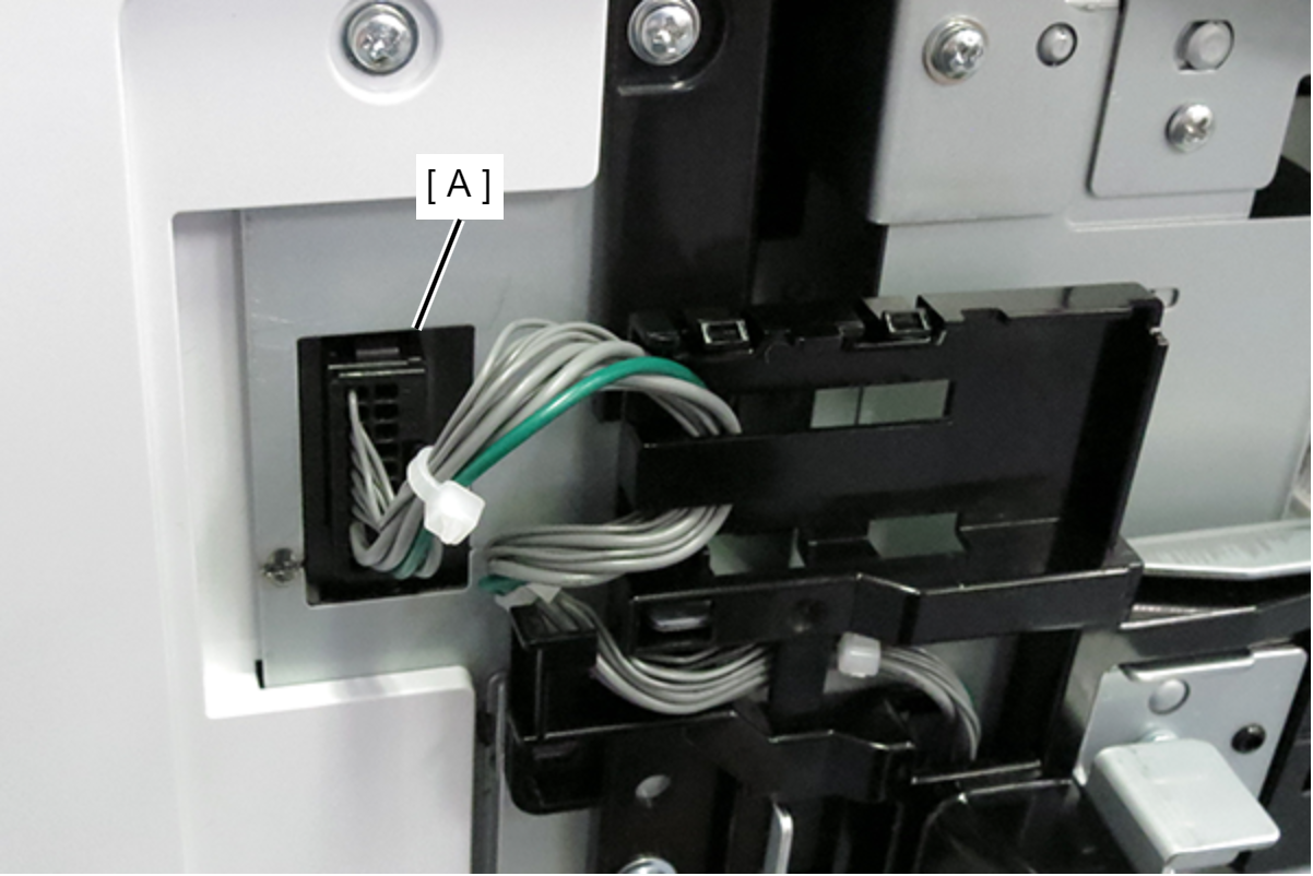
Disconnect the cables from the 2 connectors (A).
 Note / 補足
- Cable colors are as follows.
- Upper side: black
- Lower side: white
- Cable colors are as follows.
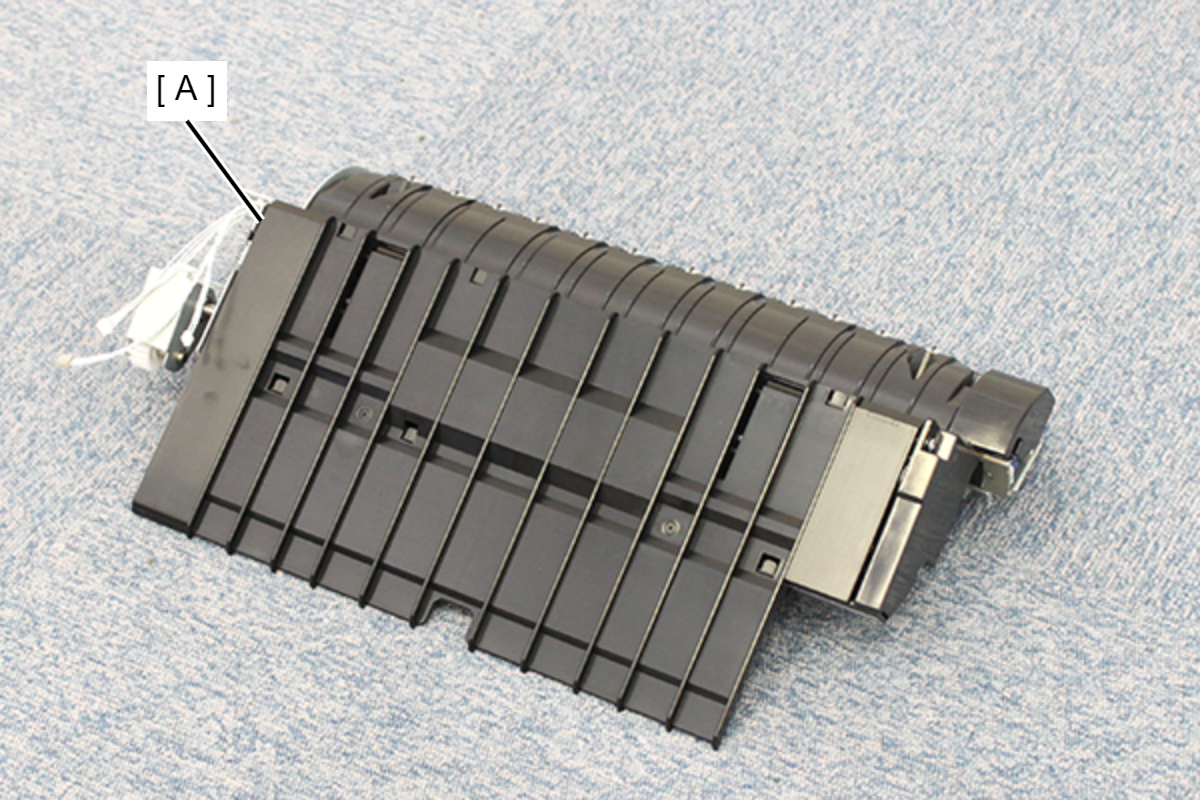
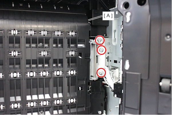
- Remove 3 screws and pull the lever (A) to remove the D3 Unit (A).
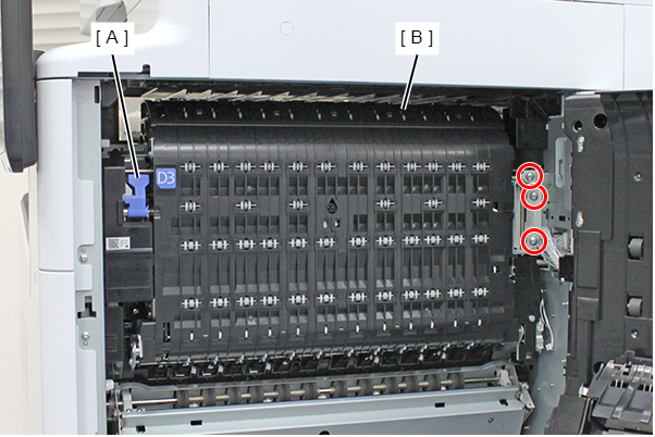
- : 4x8D/P
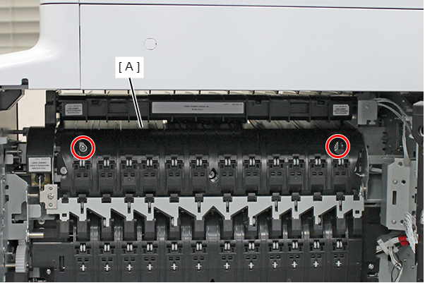
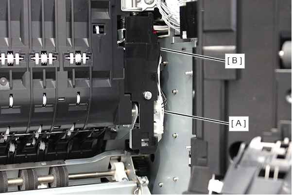
- Remove the 2 screws and remove the pre-ejection paper guide (A).
- : 3x5D/TBD
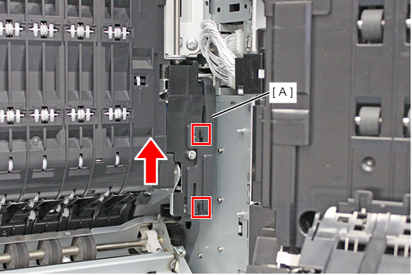
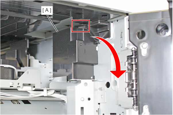
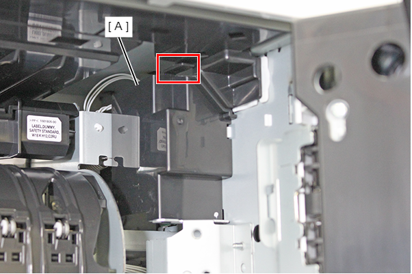
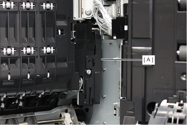
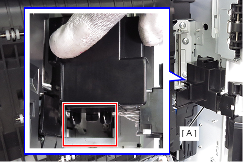
- Remove the FB cable cover (A) by rotating it in the direction of the arrow while releasing the hook.
- Prepare the floor bridge unit B (A).
- Insert the tab (B) marked with a line into the hole (A) of floor bridge unit B, and attach floor bridge unit B (C).
- Check that the frame of floor bridge unit B protrudes from the 3 holes (A) on the paper output side, and tighten the 3 screws.
- : 3x6D/P
- Tighten the 2 screws to secure Floor Bridge Unit B (A). (SX:
 )
)
- : 3x6D/P
- Connect the 3 cables of floor bridge unit B to the 3 connectors (A).
- Align the 2 dowels (A) with the two holes (B), and attach the FB cable cover (C) while rotating.
 Caution / 注意
・Confirm that the FB cable cover (A) is hooked under the FR holder (B).

If the FB cable is too deep, it can be restored by raising the FR holder (A).

・The hook of the FB cable cover (A) is hooked.
- Align the hinge dowels with the two positioning holes (A), close the lever side, and attach the D3 unit (B).
- Tighten the 3 screws to secure D3 Unit (A).
- : 4x8D/P
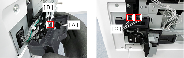
- Connect the 2 cables (A) to the connectors on the D3 unit and place them inside the hook (B).
 Caution / 注意
Be careful not to confuse the connection destination of the cable.
- Attach the D3 connector cover (A).
- Insert the tab into the frame and attach the right door cable cover (A).
- Close the Right Door Unit.
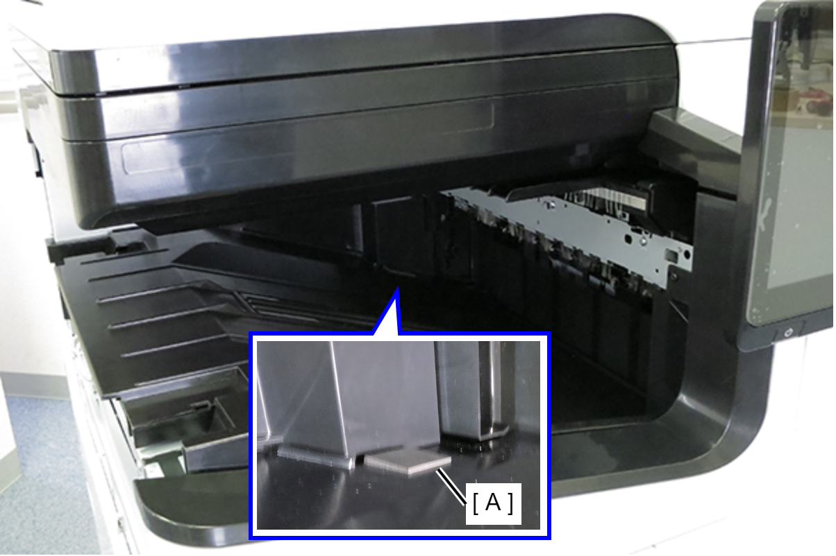
- Attach the rubber pad (A) to the position shown in the diagram on the FD Stacker Assy.
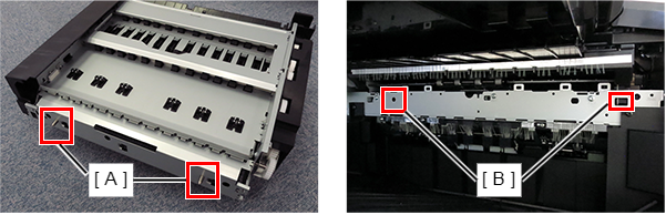
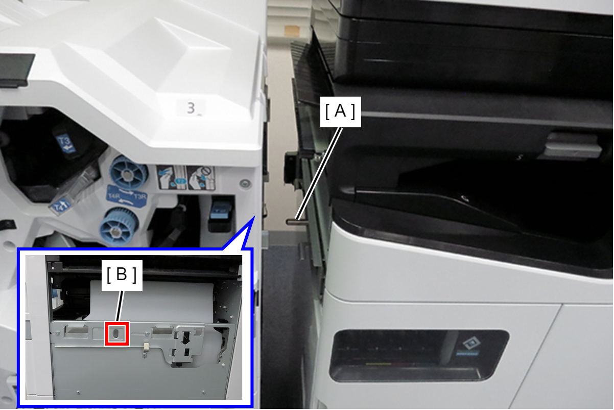
- Place the left cover (A) of floor bridge unit A on the upper part (B) of the FD inner cover and slide it in the direction of the arrow to attach the floor bridge unit A.

 Assembly / 組み立て
Insert the 2 positioning pins (A) of floor bridge unit A into the 2 holes (B) of the main unit.
- Align the dowels with the 2 positioning holes, and secure the Floor Bridge Unit A (B) with 2 screws.
- : 3x10DW/P
Note / 補足Reuse the screw removed in Step 1.
- Attach the clamp (A) and route the cable of floor bridge unit A.
- Connect the 2 cables of floor bridge unit A to the 2 connectors (A).
- Attach the FB paper guide (A) to the floor bridge unit A (B) with the 3 hooks.
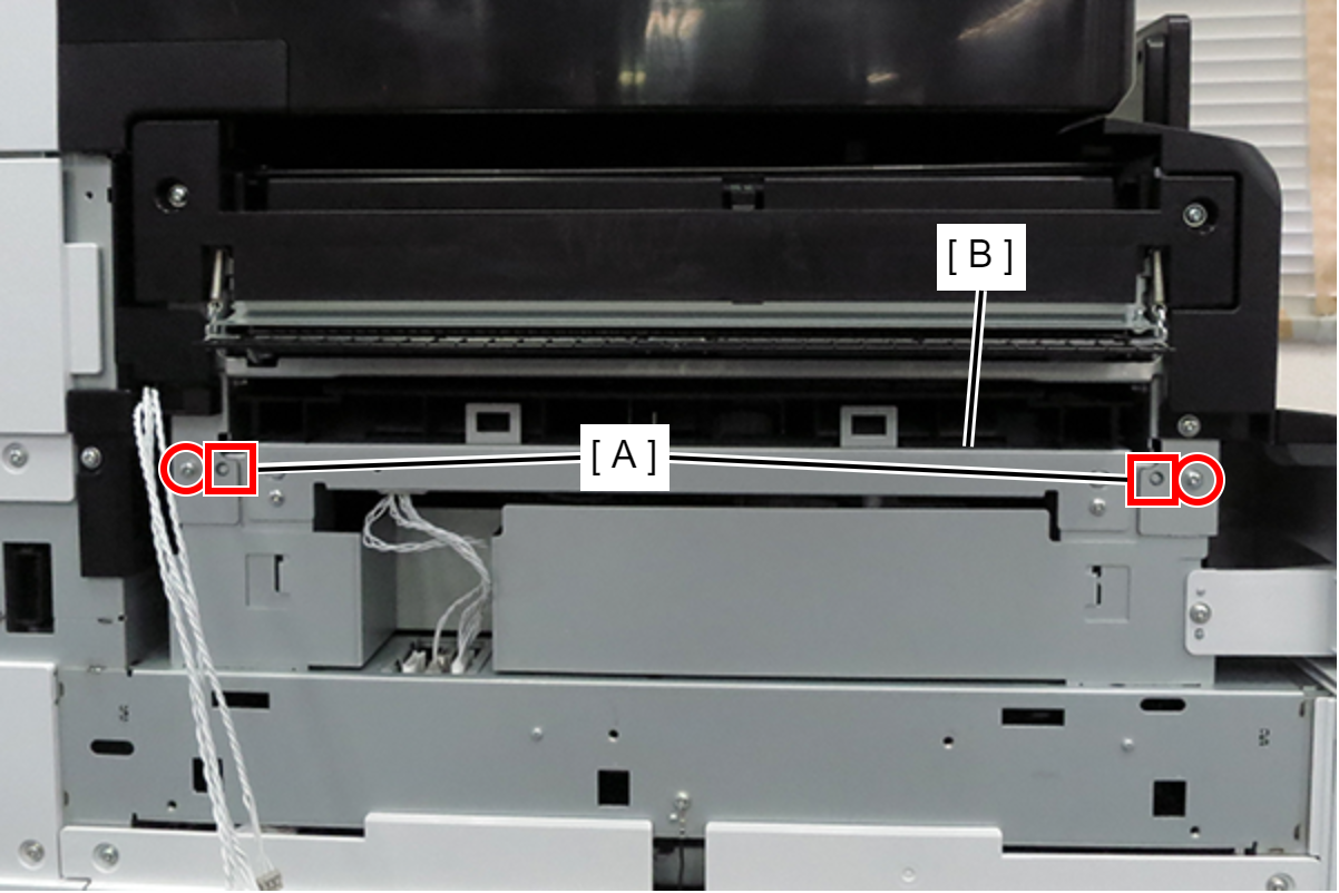
- Align the dowels with the 2 positioning holes (A), attach the paper feeding position adjustment plate (B), and temporarily secure it with 4 screws.
- : 4x8D/P
- Align the protrusion (A) of the paper-passing position adjusting plate with the center of the scale (B), and fully tighten the 4 screws to fix the paper-passing position adjusting plate.
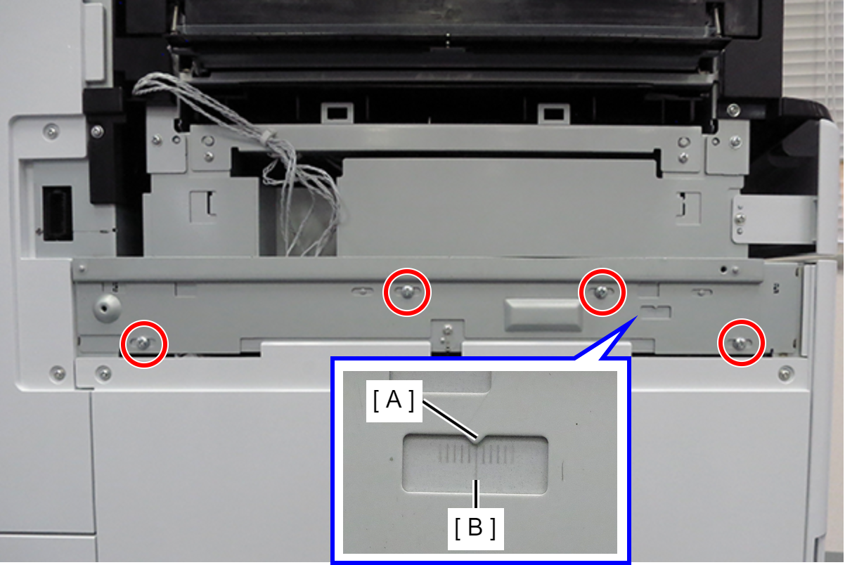
- : 4x8D/P
- Align the dowels with the 2 positioning holes (A), attach the connecting plate (B), and secure it with 2 screws.

- : 4x10DC/P
- Pass the cable of connecting plate through the hook and connect it to the connector (A) on the main unit.
- Align the tab (A) of the drawer cable cover with the hole (B) of the connecting plate and attach it, and fix it with the 2 hooks (C).
- Align the two holes marked B on the finisher grounding plate (A) with the 2 dowels on the floor finisher, and secure with 1 screw.
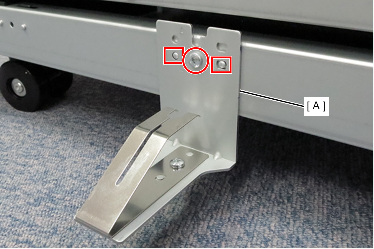
- : 4x8D/P
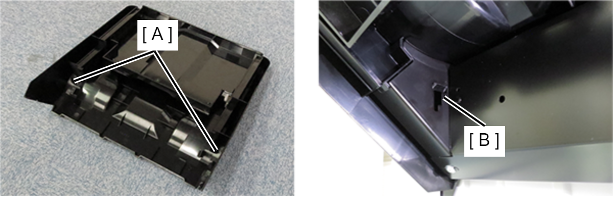
- Attach the finisher lower tray (A) to the floor finisher.
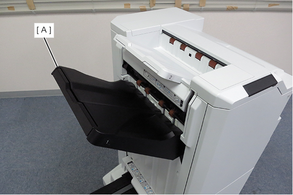 Assembly / 組み立て
Align the 2 hooks (A) on the bottom tray of the finisher with the 2 holes (B) on the floor finisher and fix them.
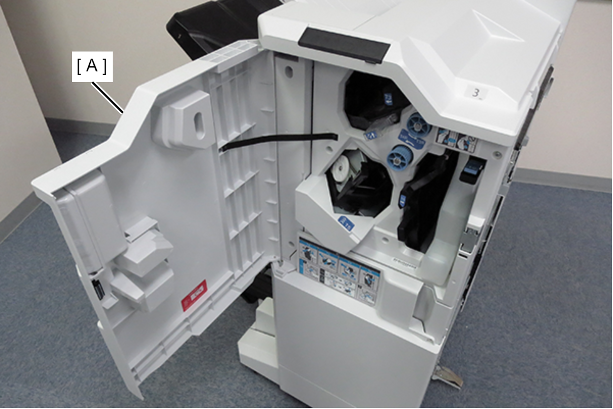
- Open the front cover (A) of floor finisher.
- Insert the staple cartridge (A) into the staple unit (B).
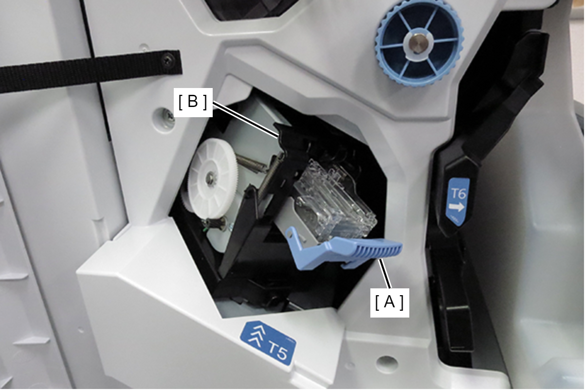 Check Point / チェックポイント
When using the saddle unit and floor punch unit, install the saddle unit and floor punch unit before installing the floor finisher.
- Remove 1 screw and pull out the slide lock (A).
- : 4x8D
- Align the positioning pin (A) on the main unit with the hole (B) in the floor finisher, and connect the floor finisher to the main unit.
- Push in the slide lock (A) and tighten the screw to secure the floor finisher (B) to the main unit (C).
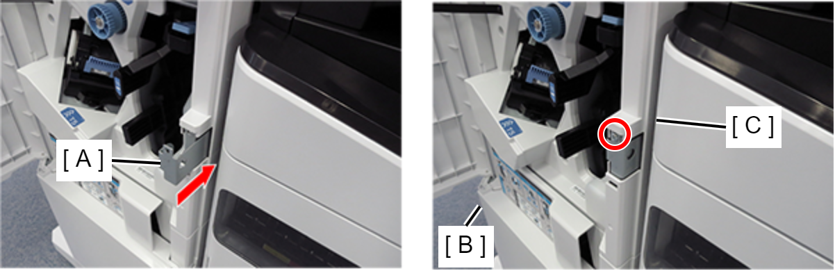
- : 4x8D
- Close the front cover.