20105 Side Registration Adjustment
Adjust the misalignment of the paper feeding position with respect to the head center position.
 important / 重要 important / 重要 |
|
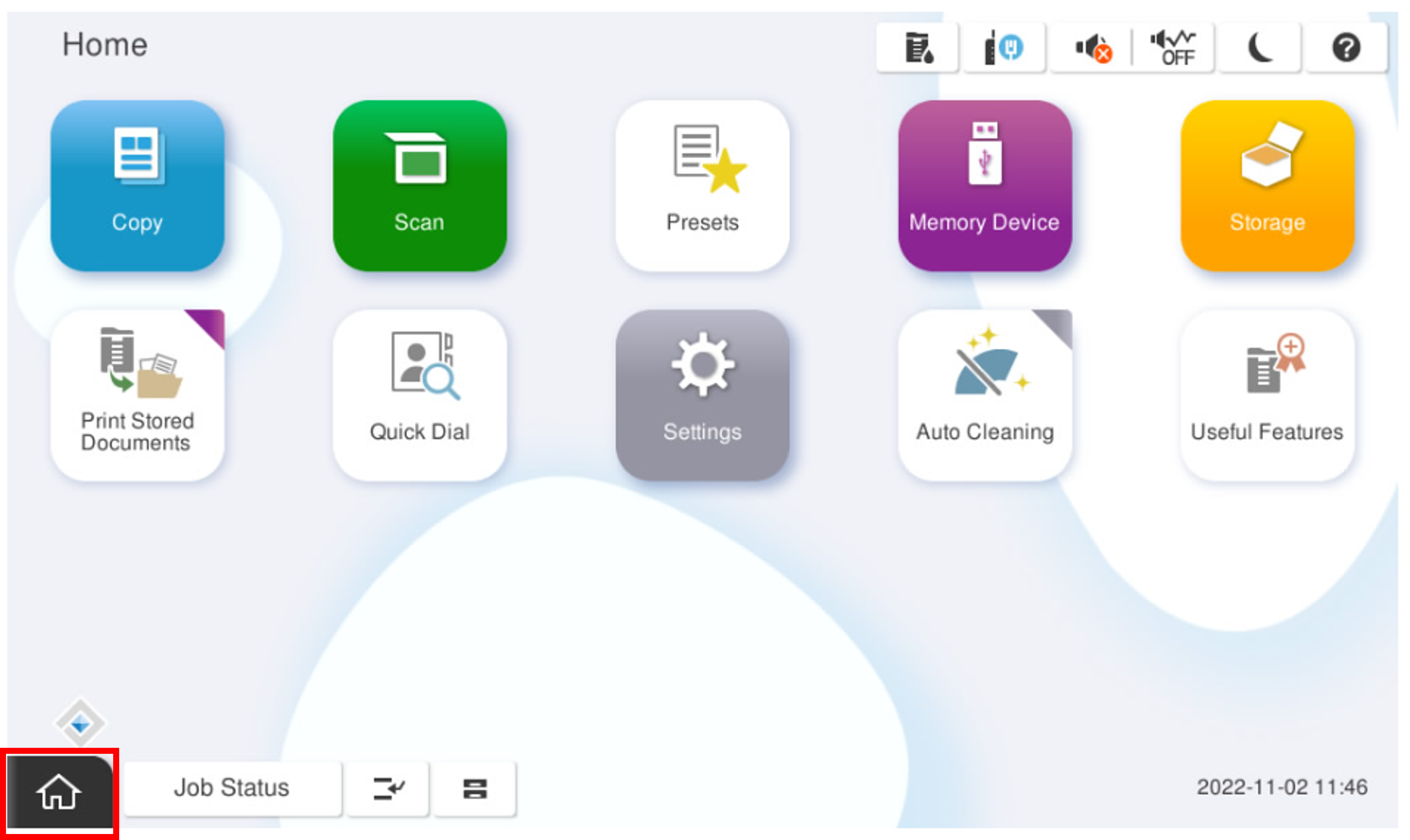
- Start the installation mode.
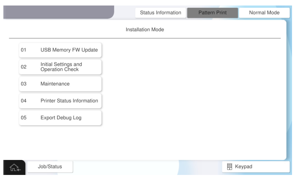
- Select [02 IInitial Settings and Operation Check].
- Select [Printer / Additional Cassette] tab.
- Select [20105 Side Registration Adjustment].
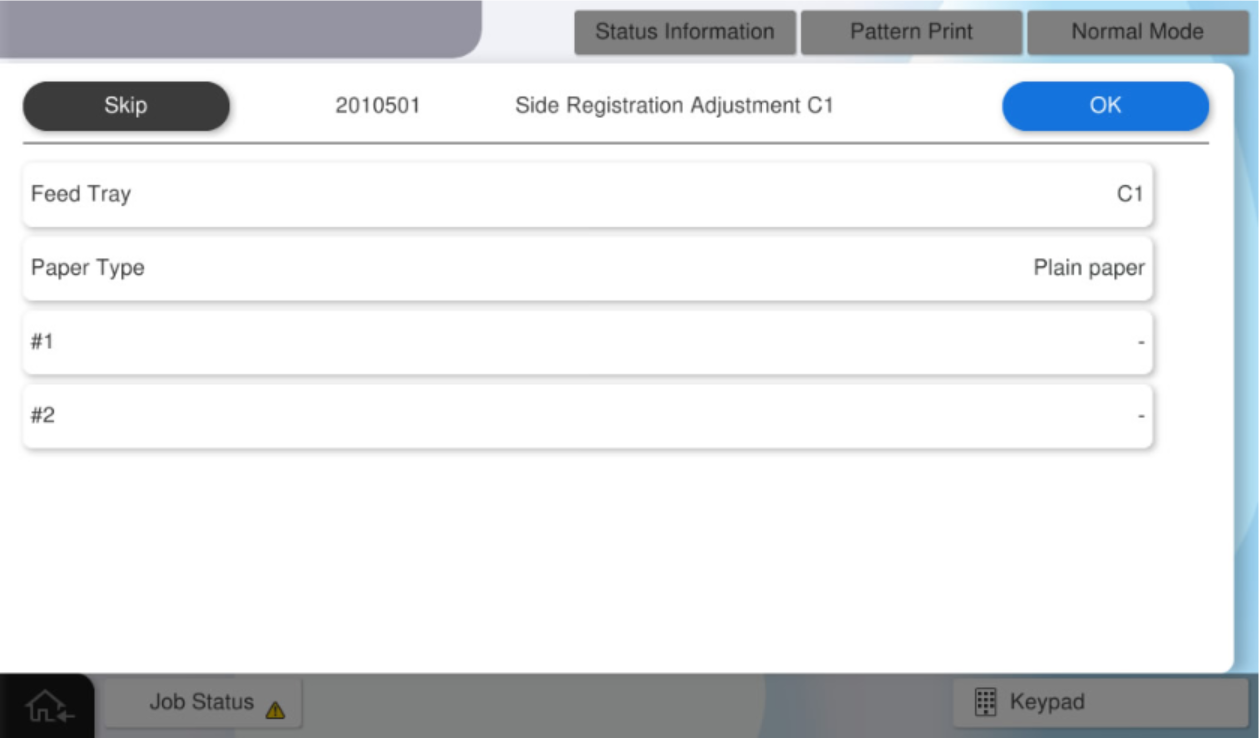
Select the menu button that supports to the paper tray and paper type for which perform the adjustment.
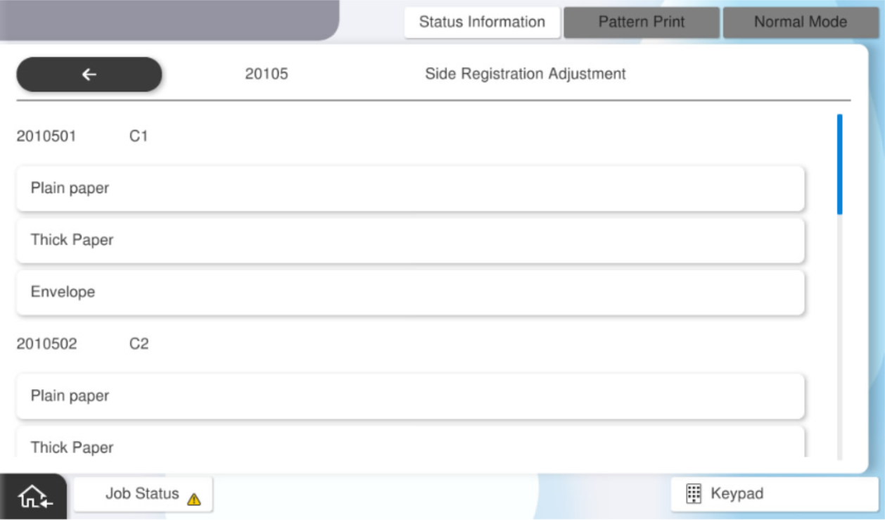
The selectable menus are as follows:
Feed Tray Paper Type Available Paper Sizes C1 Plain Paper, Cardboard, Envelope A4 (Vertical), Letter (Vertical) C2 C3 C4 MP Tray Plain Paper, Cardboard, Envelope Full tray (double sided) Plain Paper(Duplex), Cardboard(Duplex)  Note / 補足
If you select "Cardboard" or "Envelope" as the paper type, refer to the following and performed adjustments.
Reference: TBD
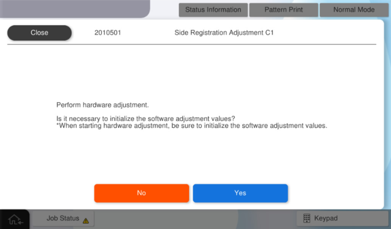
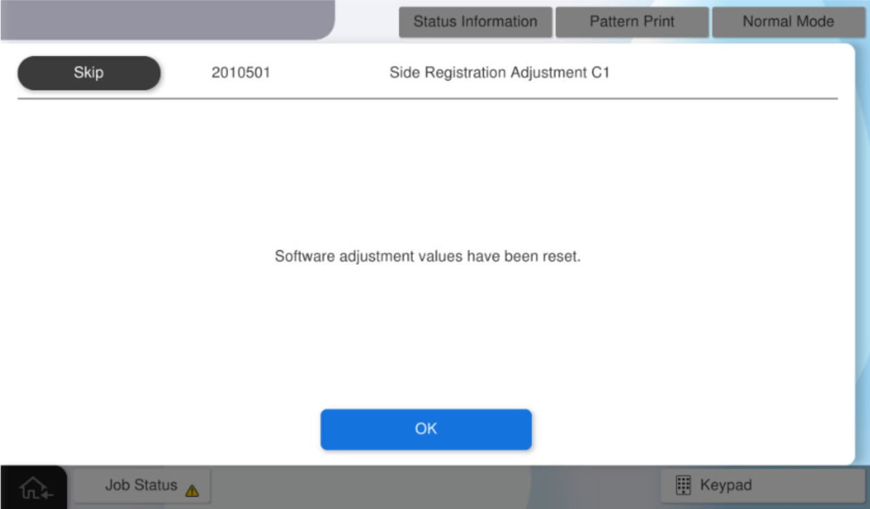
Press [Yes] to initialize the software adjustment values.
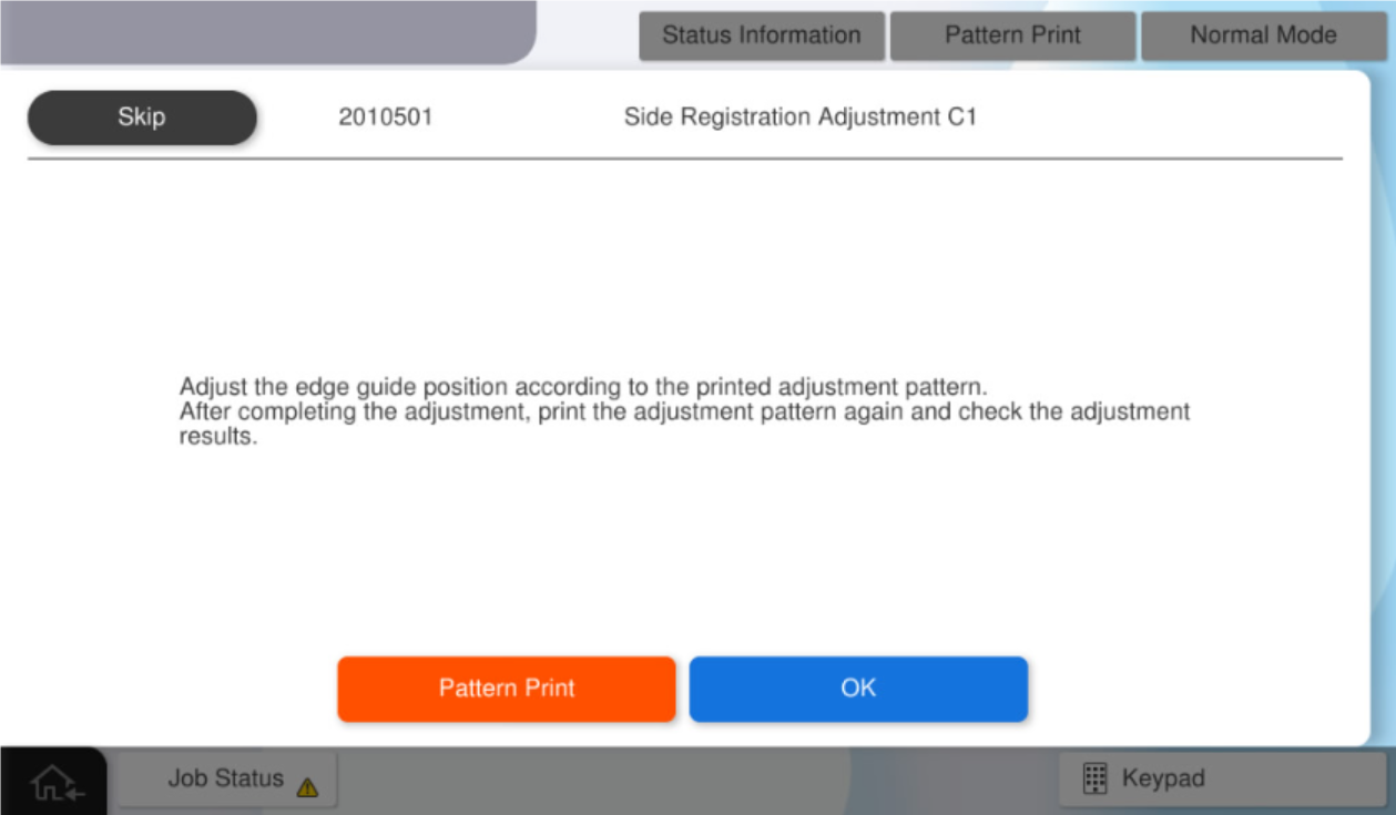
Press [OK].
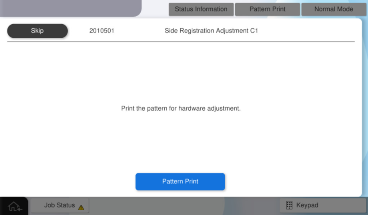
Press [Pattern Print].
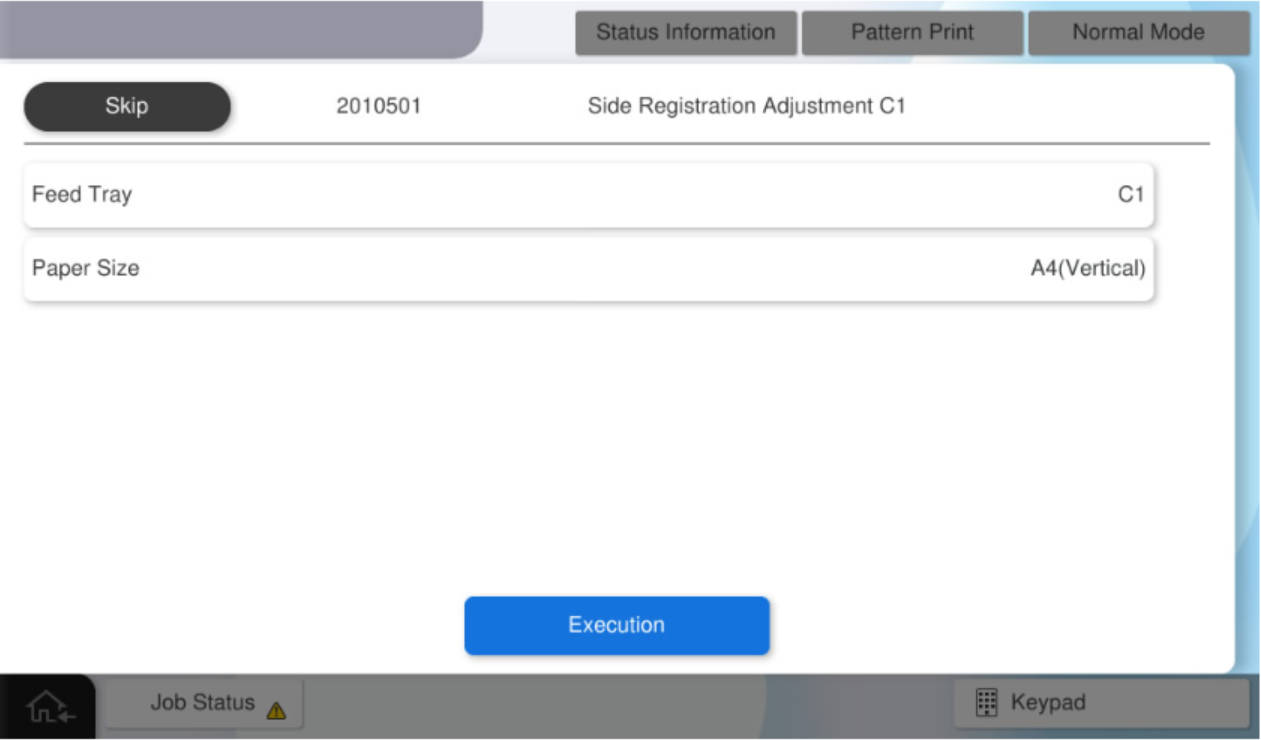
After select the paper size, press [Execution] to print a pattern for hardware adjustment.
 Check Point / チェックポイント
The paper tray cannot be changed.
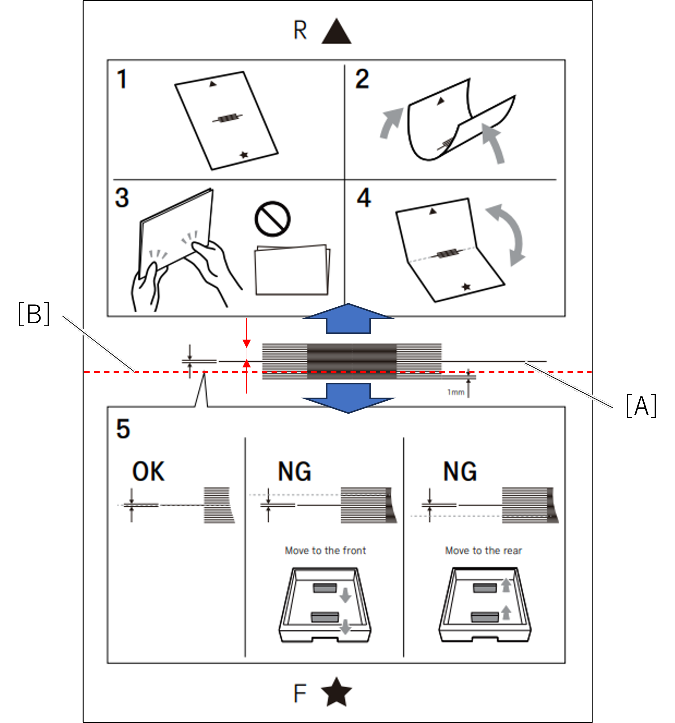
Fold the printed adjustment pattern so that the short edge (red line) of the paper is on the inside.
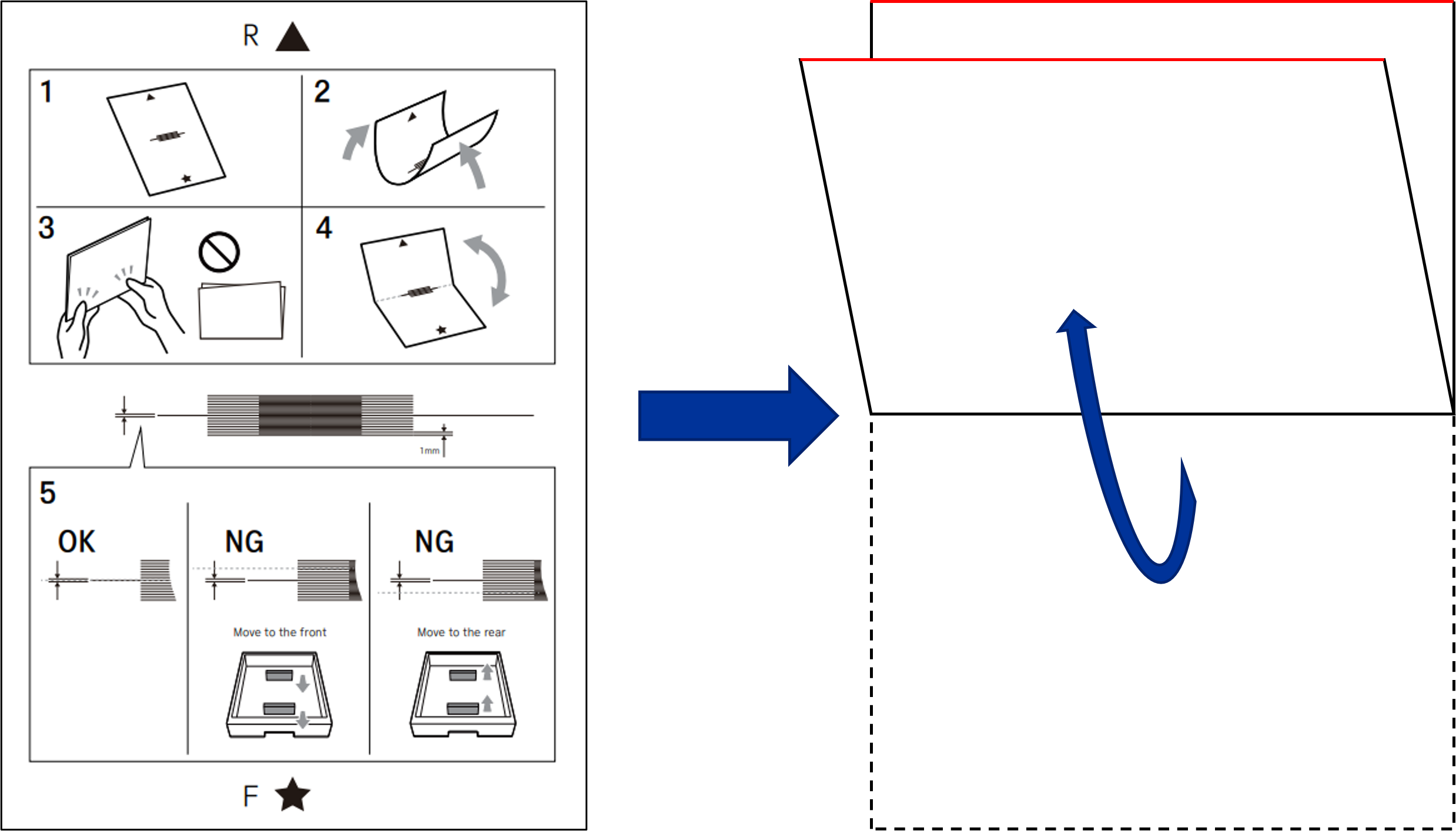
Judgment whether adjustment is necessary based on the adjustment pattern bent in step 10.
If adjustment is required (NG), proceed to step 13.
If adjustment is not required (OK), proceed to the next step.The judgement method of the adjustment results
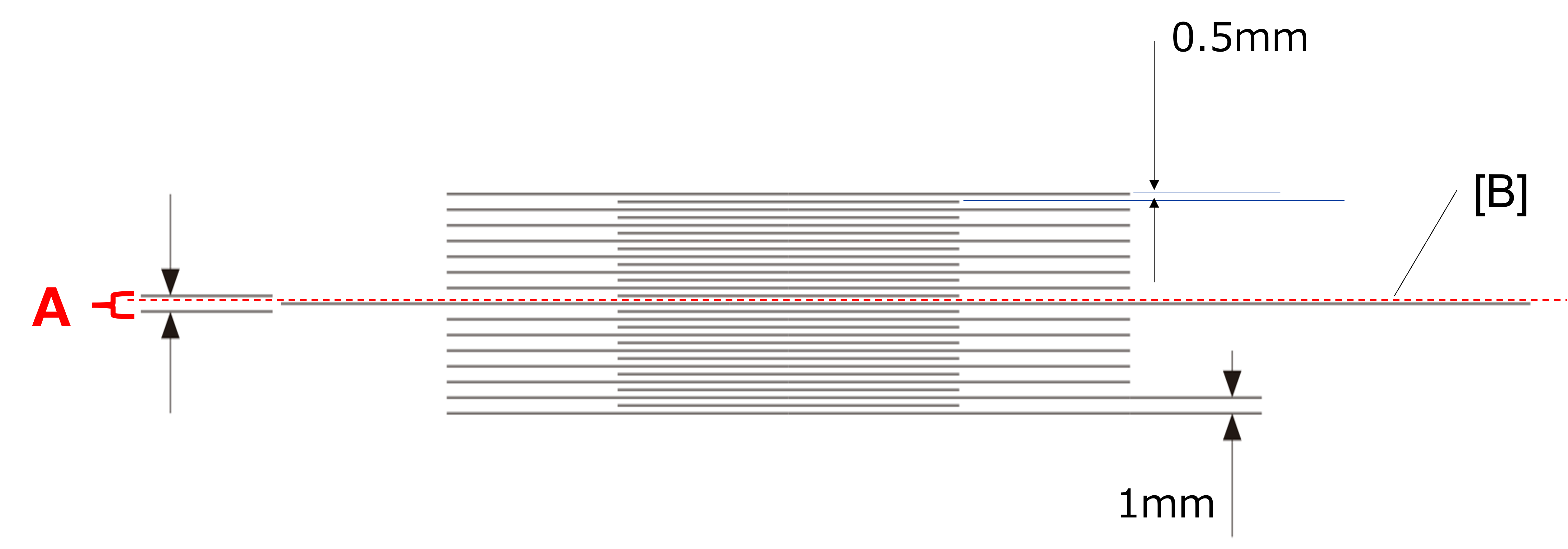
Failed (NG): The fold line of the adjustment pattern (B = red dashed line) is not within the range of A.
Pass (OK): The fold line of the adjustment pattern (B = red dashed line) is within range A.
Determined the amount of paper guide movement and movement direction based on the adjustment pattern.
The determination method of amount of paper guide movement
Check the distance between the center line (A) and the fold line (B = red dashed line) on the scale to calculate the margin adjustment amount.
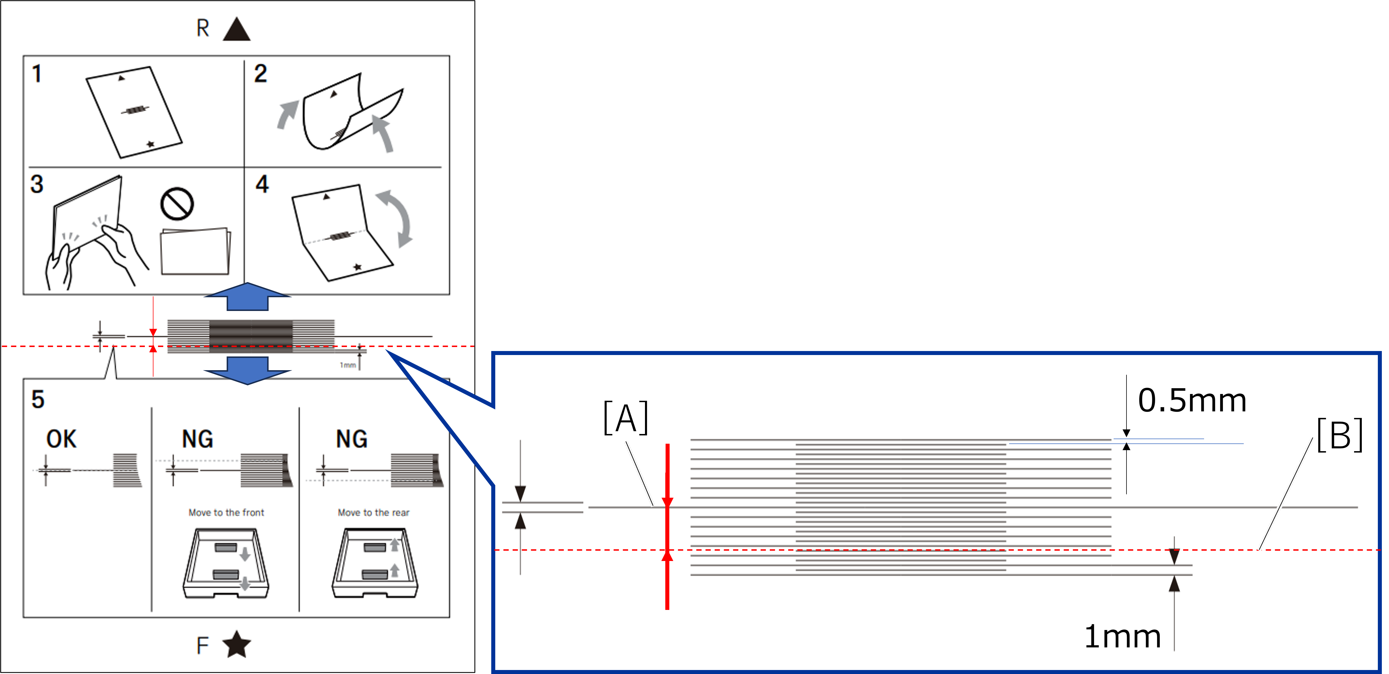
Distance between the long lines on the scale of the adjustment pattern: 1 mm.
Distance between long and the short lines of the adjustment pattern: 0.5 mm.
The determination method of paper guide movement direction
The fold line (B = red dashed line) is above the center line (A): move the paper guide toward the front of the printer.
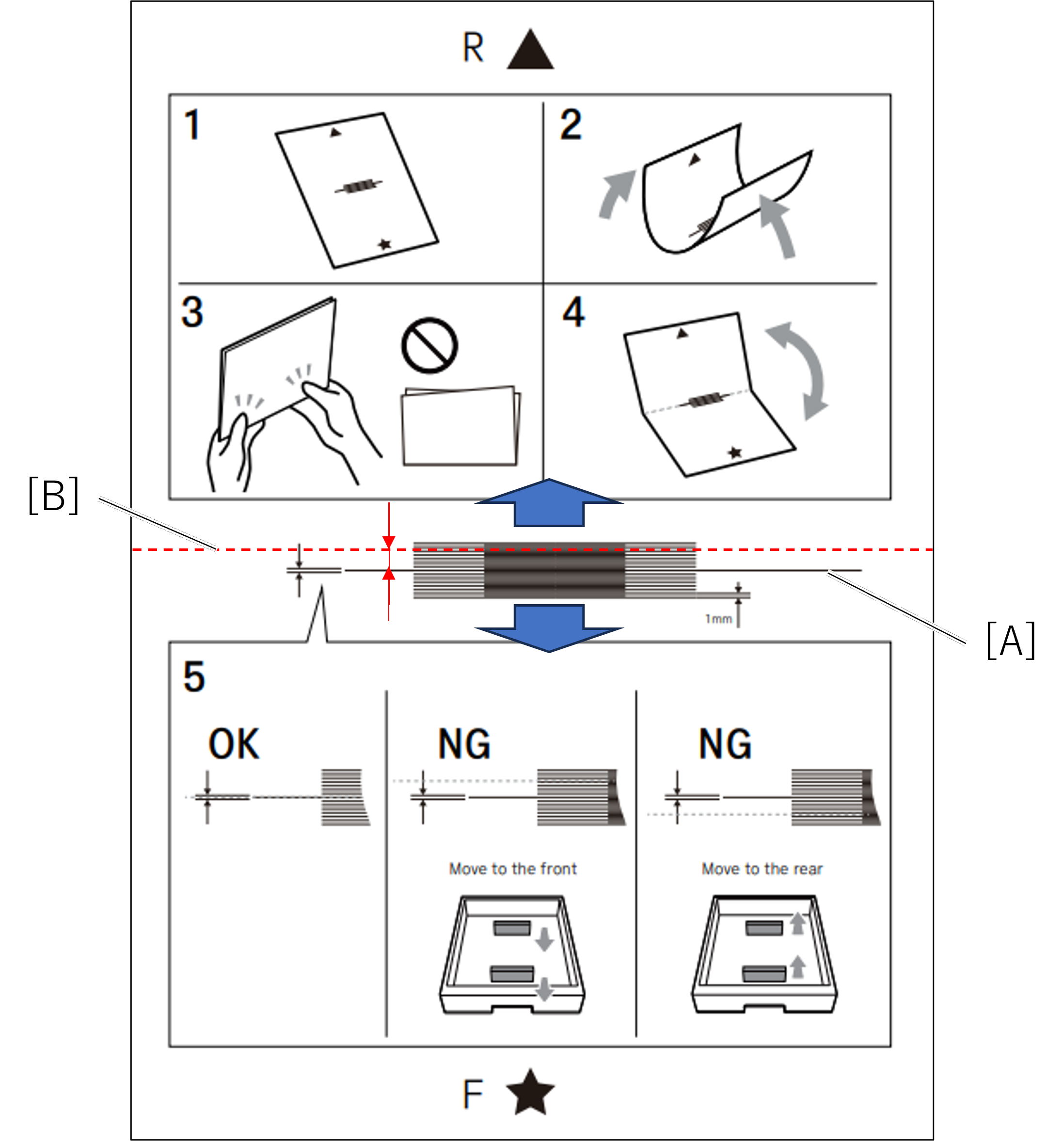
The fold line (B = red dashed line) is under the center line (A): move the paper guide toward the rear of the printer.
Change the paper guide position of the target paper feed device based on the margin adjustment amount.
Note / 補足- For details on the procedure for changing the paper guide position, refer to the following.
- For details on the procedure for changing the paper guide position, refer to the following.
Press [Pattern Print] in service support mode again.
After select the paper size, press [Execution] to print a pattern for hardware adjustment.
Using the printed adjustment pattern, judge the results. using steps 10 and 11.
If the adjustment result is NG, repeat steps 12 and 13.
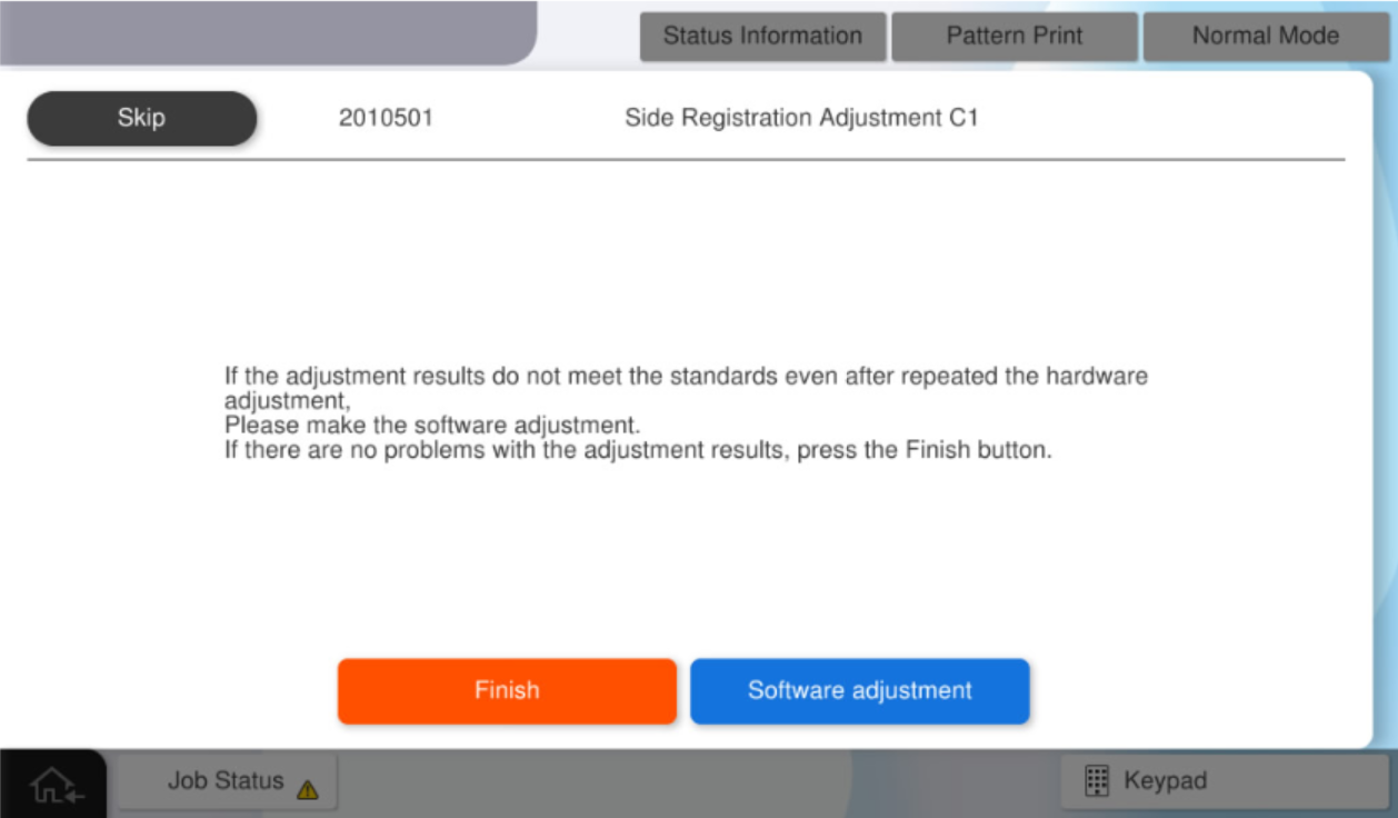
If the adjustment results are OK, press [OK].Note / 補足If the adjustment result is NG and If the problem does not improve or cannot be adjusted, please understand the important information at the beginning of this page and perform software adjustments. (in this case, press [OK]).
Press [Finish] or [Software adjustment].
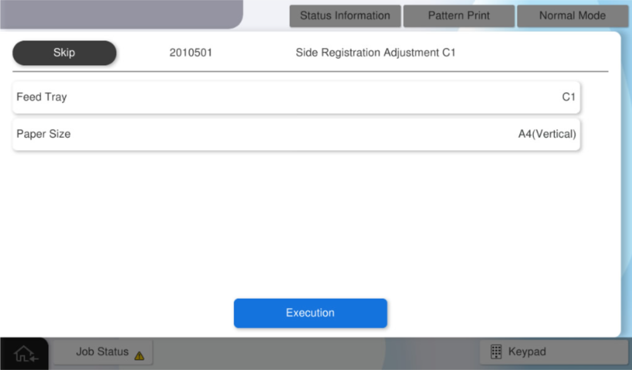
Press [Pattern Print].

After select the paper size, press [Execution] to print a pattern for software adjustment.
Check Point / チェックポイントThe paper tray cannot be changed.
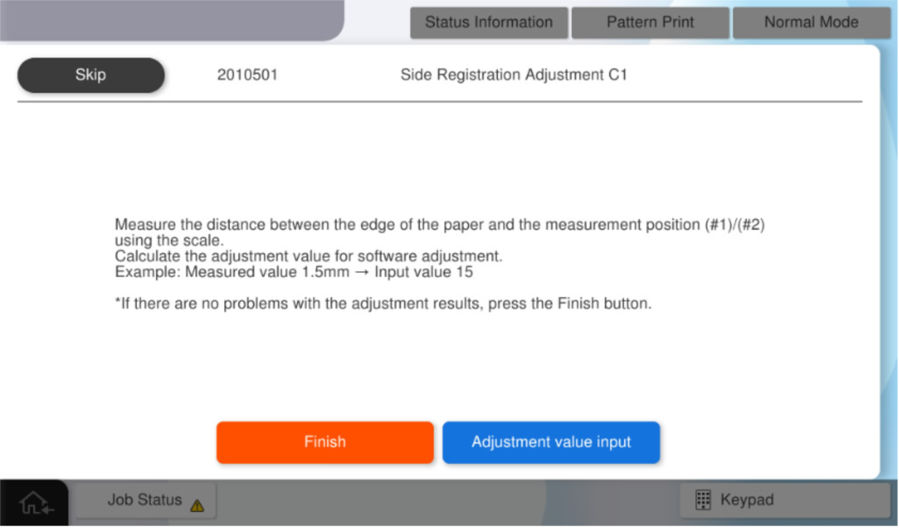
Measure the margin amount of #1 and #2 on the adjustment pattern.
Check Point / チェックポイント- When measurements, be careful to the front and back sides of the adjustment pattern.
- 1-sided (1st side): Measure on the side with "Simplex side / surface" printed on it.
- 2-sided (2nd side): Measure on the side with "Duplex side / rear side" printed on it.
- Standard value: The margin difference between the front and rear sides of the product is within 0.5mm.
Note / 補足- The method for measuring the amount of blank space is as follows.
- Distance from the paper edge to the "#1 mark"
- Distance from the paper edge to the "#1 mark"

- When measurements, be careful to the front and back sides of the adjustment pattern.
Calculate the panel input value.
Note / 補足- The calculation formula and example of the input value are as follows.
- Input value = measurement value x 10
- e.g.) Measurement value = 7.5mm, Input value = 75
- The calculation formula and example of the input value are as follows.
- Press [Adjustment value input].
- Press [#1] and enter the input value #1 calculated by step 4.
- Press [#2] and enter the input value #2 calculated by step 4.
Press [OK] to reflect setting value.
 Check Point / チェックポイント
- The paper tray cannot be changed.
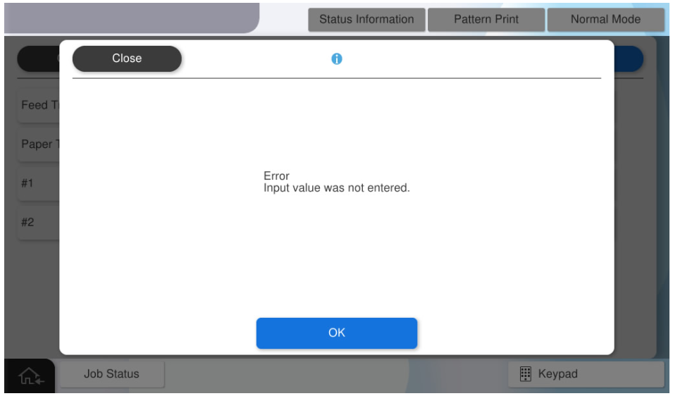
If you press [OK] when all the values have not been entered, the following screen will be displayed.
Note / 補足In the above-described procedure of the software adjustment, an adjustment for outputting an image to the center of the sheet is automatically performed by inputting a measured value of the margin amount to a panel as an input value.
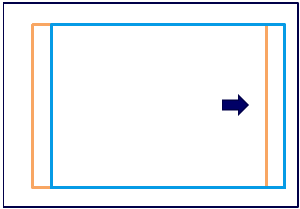
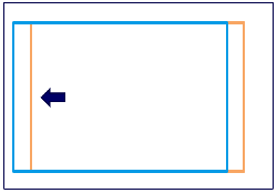
If you want to shift the image to any position (blue frame), determine the input value by referring to the following adjustment value specifications.Internal adjustment value = (input value #2-input value #1) / 2
To shift the image 1 mm rightward from the current position (orange frame): Internal adjustment value = 10
To shift the image 1 mm rightward from the current position (orange frame): Internal adjustment value =-10
Press [Pattern Print] in service support mode again.
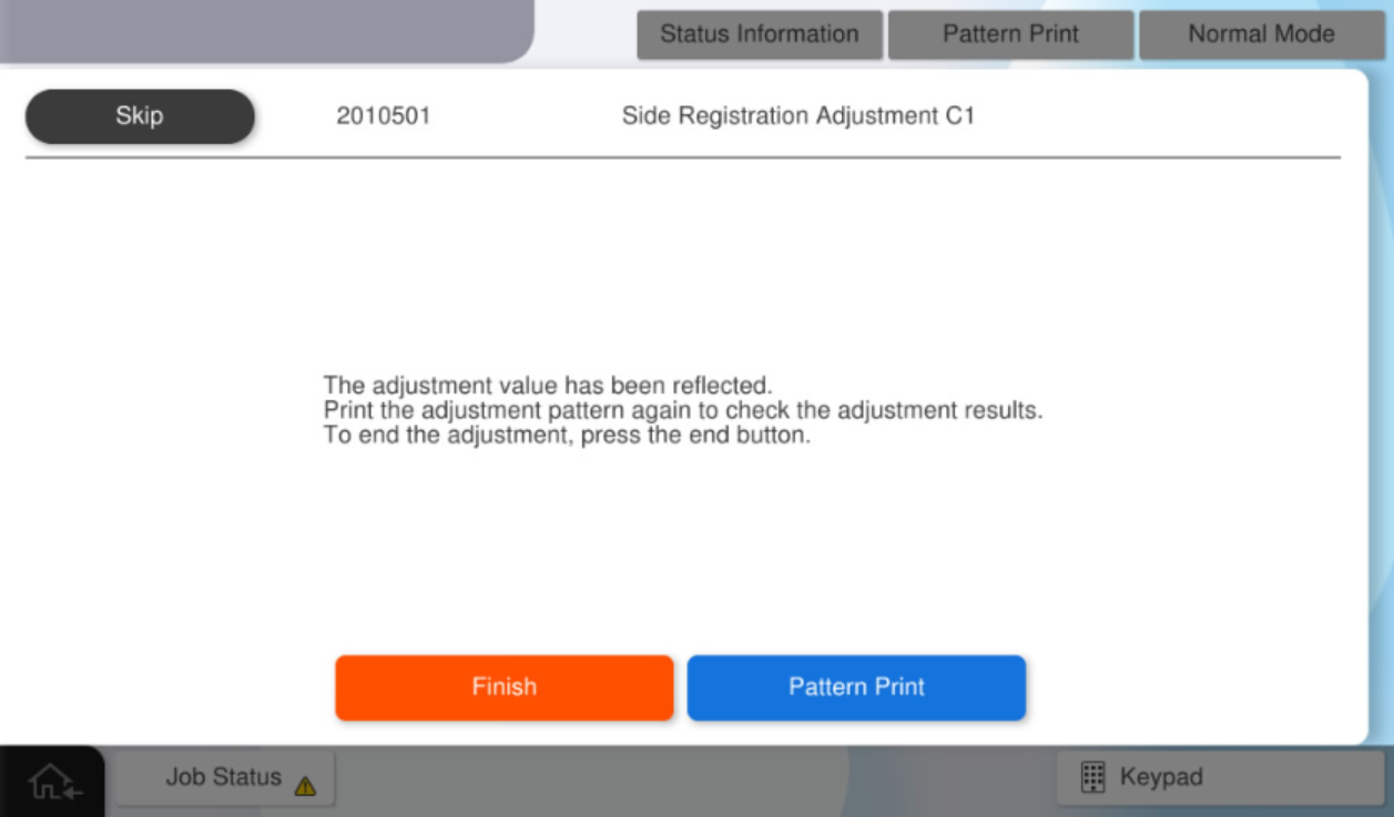
- After select the paper size, press [Execution] to print the adjustment pattern.
Using the printed adjustment pattern, judge the results.
If the adjustment result is NG, repeat steps 20 to 25.
If the adjustment results are OK, press [Finish].Check Point / チェックポイントStandard value: The margin difference between the front and rear sides of the product is within 0.5mm.