High Capacity Unit Installation Procedure
 Caution / 注意 Caution / 注意 |
Be sure to check the following precautions before installation.
|
Items to Prepare
- High capacity Unit included items
- Phillips (+) screwdriver
- Tweezers with narrow tips
Installation Procedure
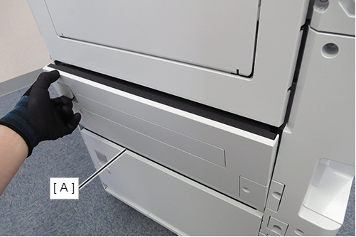
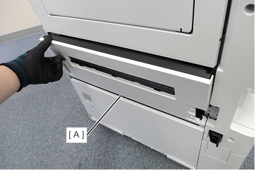
- Open the E Cover (A).
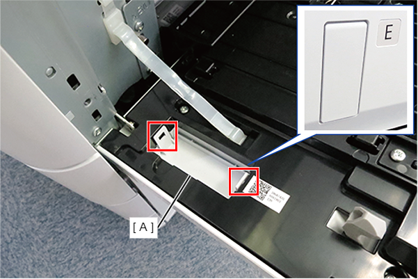
- Release the 2 hooks and remove the lock plate front cover (A).
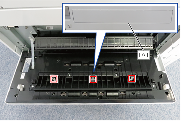
- Release the 3 hooks and remove the paper feed slot cover (A).
- Close the E cover.
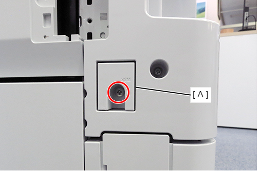
- Remove the 2 screws and remove the lock plate rear cover (A) and the lock plate rear cover sub (B).
 : 3x10T/P
 : 3x10DW/P
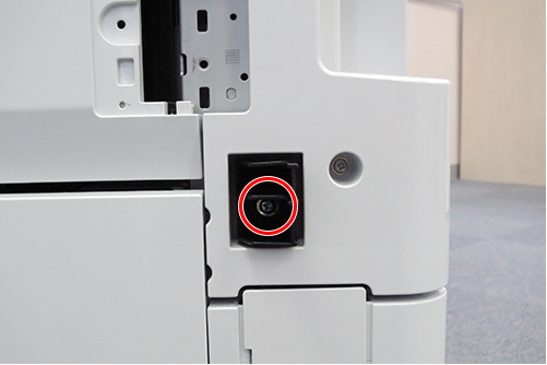
- Remove 1 screw and remove the switch lever cover (A).
- : 4x8D
- Remove 1 screw and slide rail cover (A).
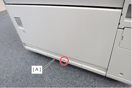
- : 4x12DC/P
- Release the hook and remove the high-capacity cable cover (A).
(Rear side)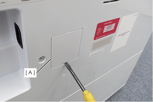
- Install the switch lever (A) and secure it with one screw.
- : 4x10DC/P
- Open the E Cover (A).
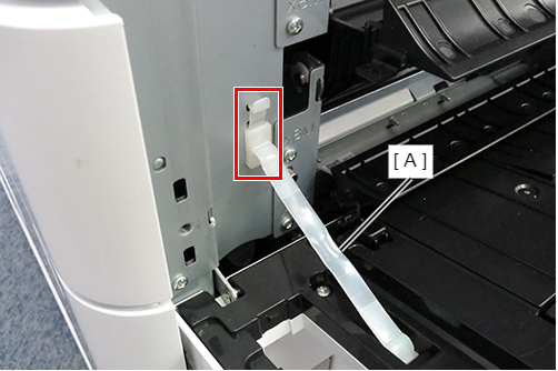
- Release the hook and remove the cover band (A) from the Main Unit.
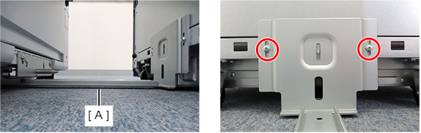
- Attach the Front Lock Metal Plate (A), align the projection with the bottom of the scale, and fix it with one screw.
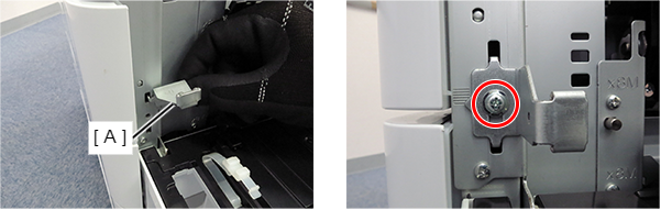
- : 4x10DC/P
- Attach the Rear Lock Metal Plate (A), align the projection with the bottom of the scale, and fix it with one screw.
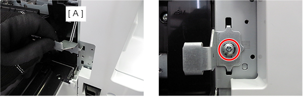
- : 4x10DC/P
- Remove the 2 screws from the slide rail mounting part on the right side of the main unit.
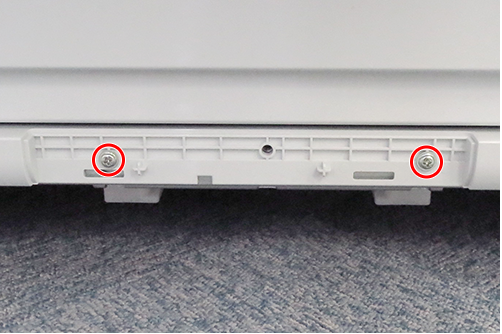
- : 4x12DC/P
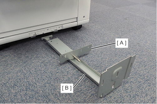
- Overlap the slide rail (A) and the slide rail guide (B) and temporarily assemble to the main unit.
- Align the 2 dowels (A) on the main unit with the 2 positioning holes (B) on the slide rail, and secure the slide rail (C) with 2 screws.
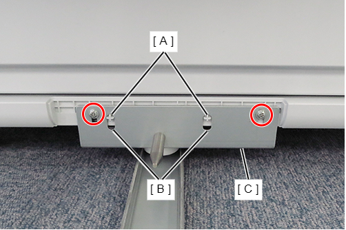
- : 4x10DC/P
 Note / 補足
Reuse the screw removed in Step 14.
- Move the high-capacity paper feed unit to the right side of the main unit, and align the dowel (B) of the high-capacity paper feed unit with the positioning hole (A) of the slide rail guide.
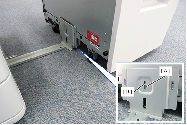
- Secure the slide rail guide (A) with 2 screws so that the bottom surface of the slide rail guide (A) is parallel to the floor.
- : 4x10DC/P
Note / 補足The height of the tightening positions of the two screws must be the same.
- Install the High Capacity Unit to the Main Unit
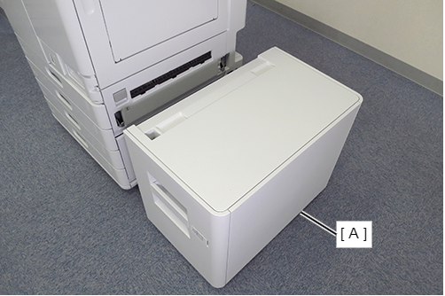 Note / 補足
To remove High Capacity Unit (A) from the Main unit, press the lever (B) to unlock it and slide the High Capacity Unit.
If the hook of the High capacity unit does not catch on the front/rear lock plate installed in steps 12/13, change the installation position of the front/rear lock plate.
Check the levelness of the High capacity paper feed unit for the main unit.
 Check Point / チェックポイント
- Horizontality of front side ① and rear side ②: ①-② = within ±1mm
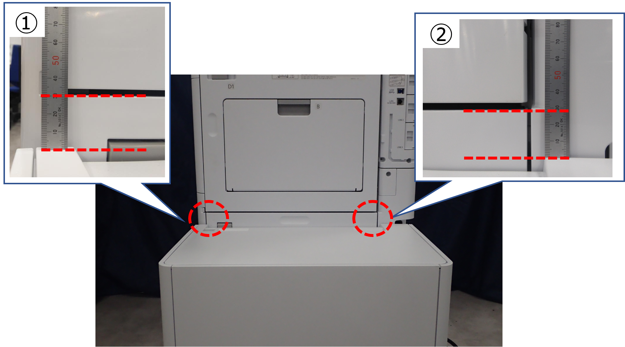
- Even if it is ±1 mm or more, there is no problem if the amount of margin is appropriate by adjusting the side registration after installing the High capacity paper feed unit.
If the margin amount cannot be adjusted appropriately, attach the spacer plate for the High capacity paper feed unit and change the height of the casters. (Procedure for changing the height of the high capacity unit)
- Horizontality of front side ① and rear side ②: ①-② = within ±1mm
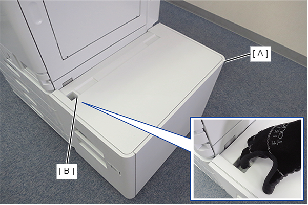
- Open the sheet cover (A) of the High Capacity Unit, fold and attach the Paper Size Labels (B).
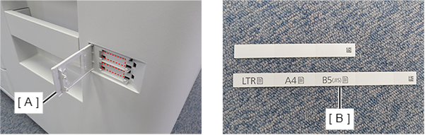 Note / 補足
The Paper Size Labels must be attached so that the paper size used by the customer can be seen.
Fold the plain sheet and attach it to the bottom.
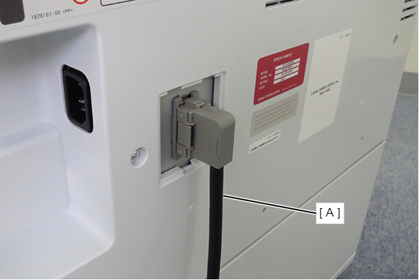
Connect the cable (A) of the High Capacity Unit to the Main Unit.
Procedure for changing the height of the high capacity unit
| Note / 補足 |
|
Bundled Items
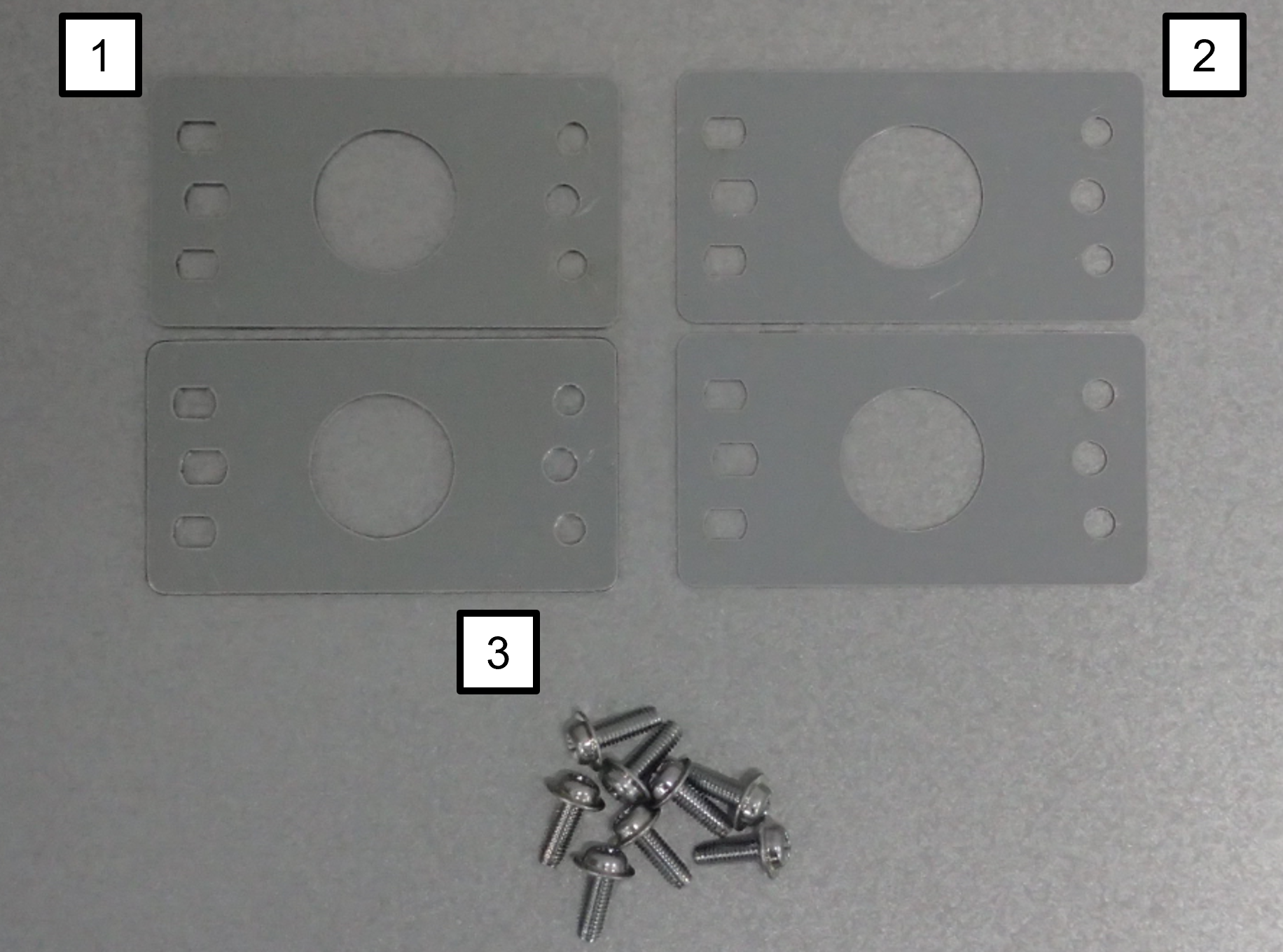
| No. | Bundled Items | Qty. |
|---|---|---|
| 1 | Spacer (2mm) | 2 |
| 2 | Spacer (1mm) | 2 |
| 3 | Screw M4 × 12 | 8 |
Tilt the high capacity unit 90 degrees with the left side (A) facing up.
 Caution / 注意
There is a risk of damage to the unit if it is turned up in a direction other than that specified.
In particular, if the top surface of the unit is turned 180 degrees so that it is installed on the floor, the wire on the paper set plate will loosen and it will not be possible to restore it.
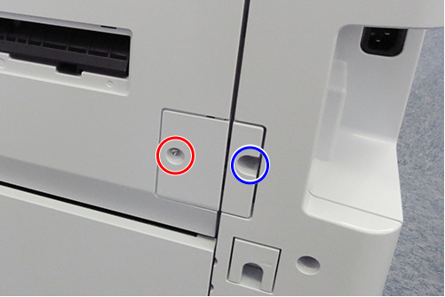
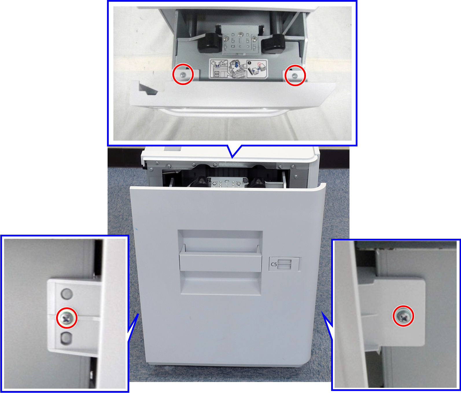
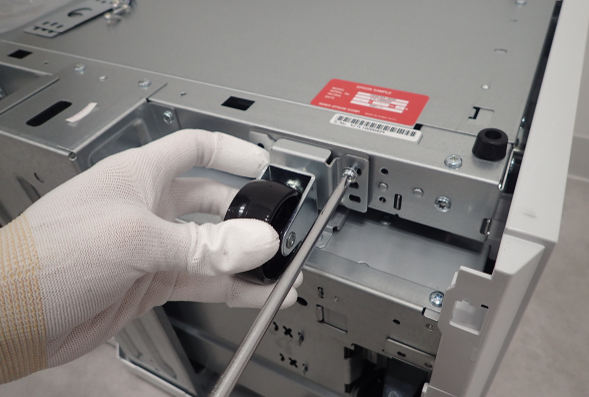
Remove the two lower casters (A) on the front and rear sides.
As an example in the figure below, the two casters (A) enclosed by the blue dashed line are on the lower side.
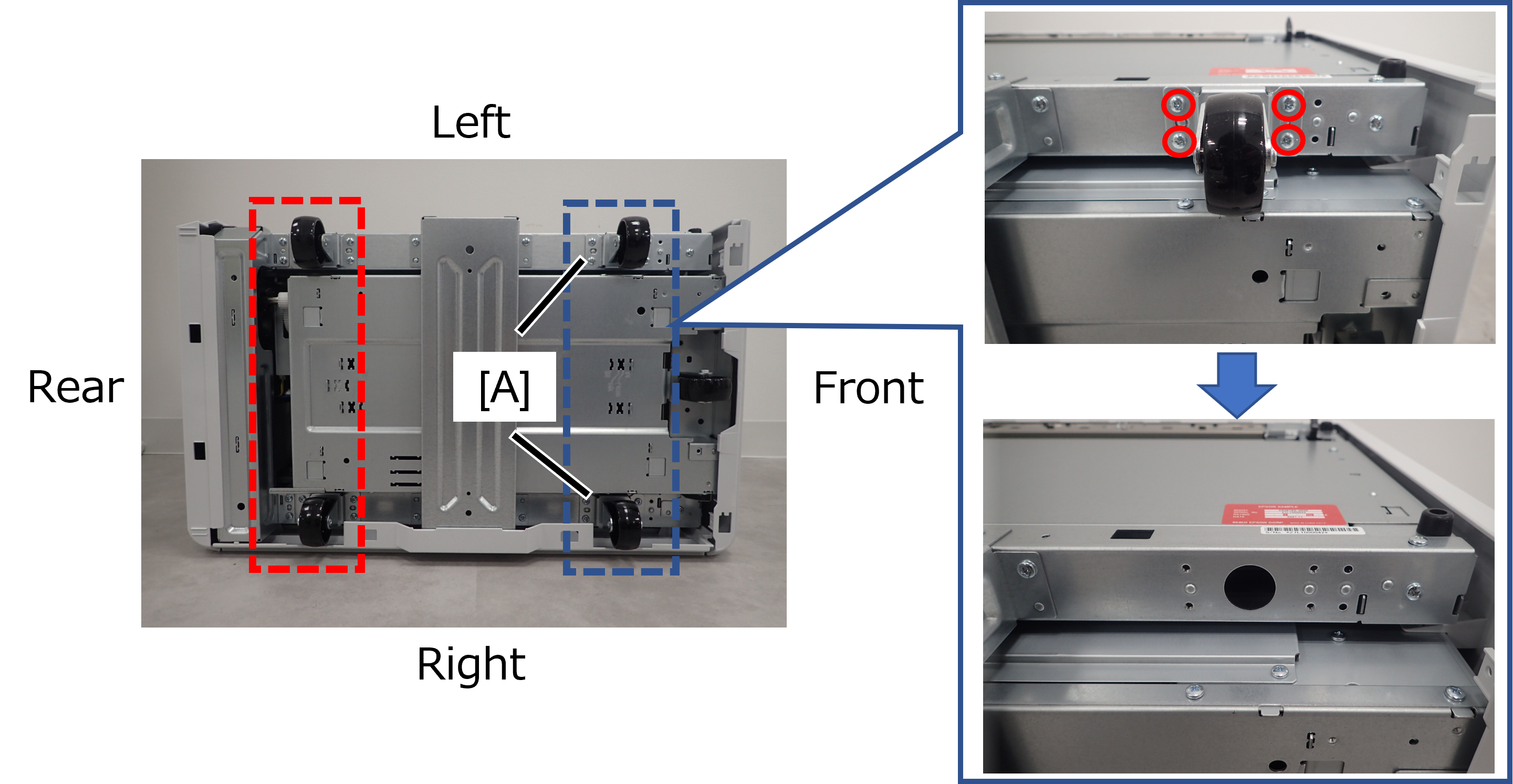 Check Point / チェックポイント
The two casters on the lower side must be uniformly height-adjusted.
The removed screws are no longer needed and can be discarded.
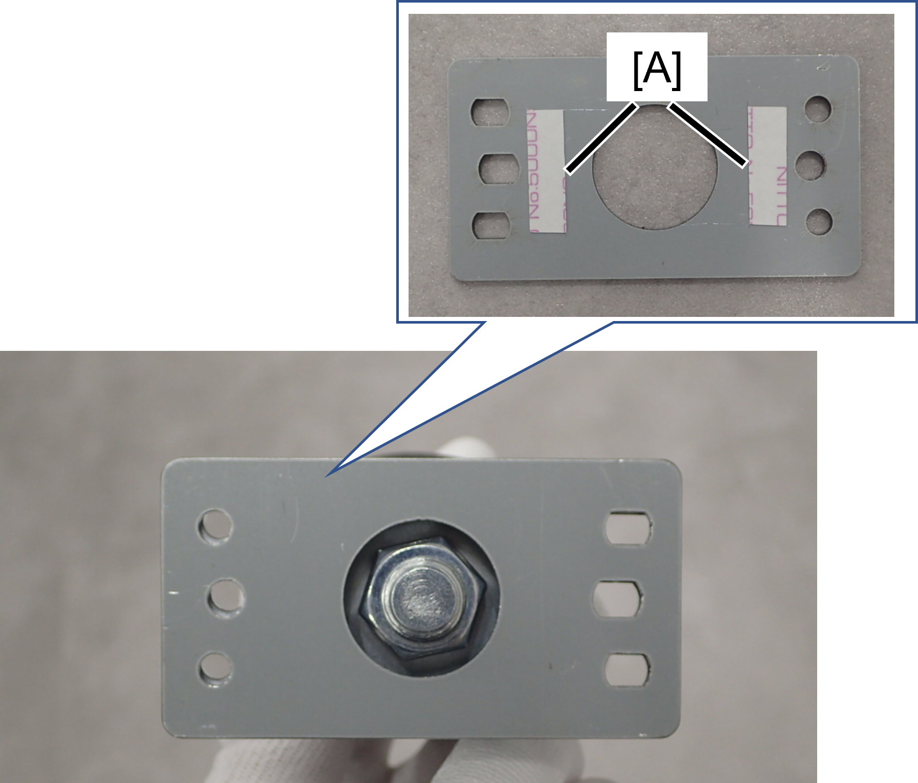
- Set the included spacer (A) in the dowel on the high capacity unit according to the height difference between the front and rear sides.
 Check Point / チェックポイント
Set the left and right side spacers to the same height.
When adjusting the height by 3mm, combine the included 1mm and 2mm spacers. At this time, it is recommended that one of the spacers be worked with double-sided tape (A) attached to the caster side, as handling the two spacers will deteriorate the workability.
- Fix the left and right casters with the included screws (M4x12) with the spacers in between.
Return the high capacity unit to its original position and attach it to the main unit.
Check Point / チェックポイントIf the hook of the High capacity paper feed unit does not catch on the lock plate front/rear, change the installation position of the lock plate front/rear.