Inner Punch Unit Installation Procedure
 Caution / 注意 Caution / 注意 |
Be sure to check the following precautions before installation.
|
Items to Prepare
- Inner Punch Unit Bundled
- Phillips (+) screwdriver
Installation Procedure
| Caution / 注意 |
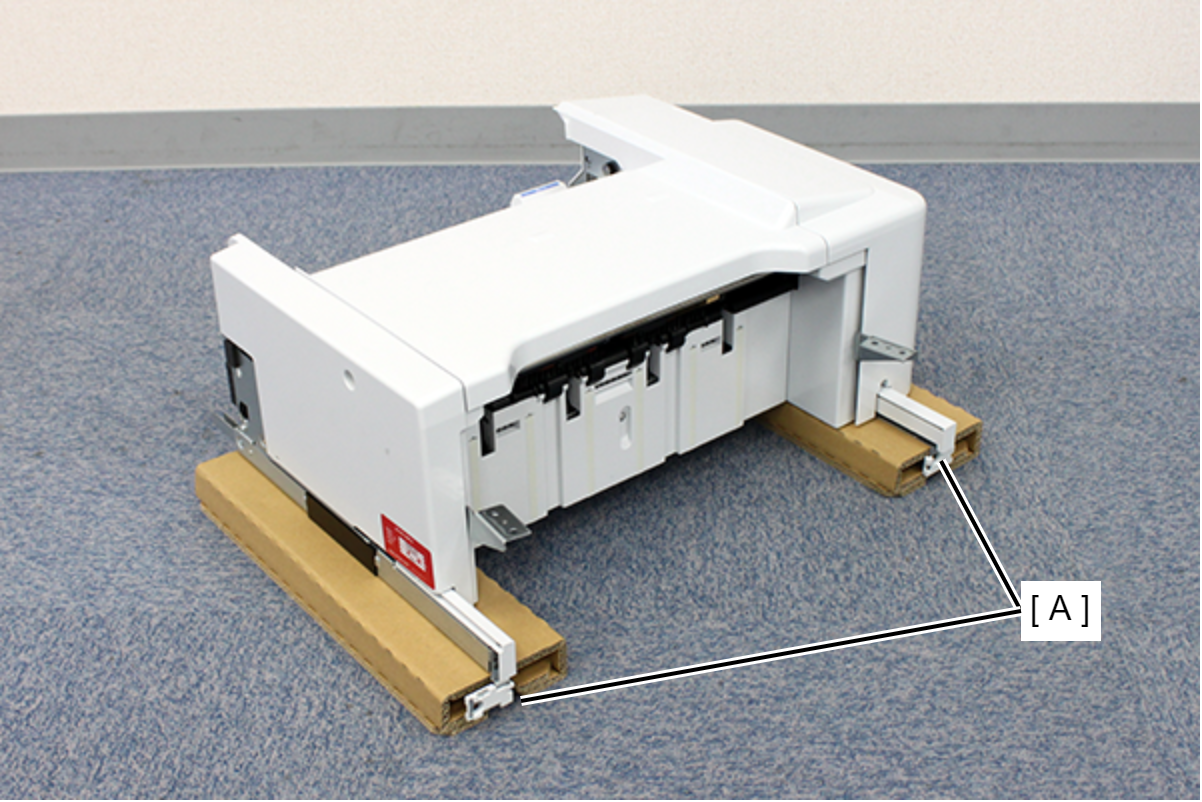
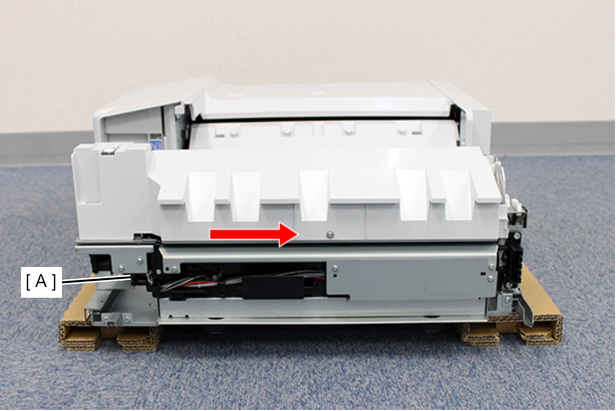
Place the inner finisher on top of the packing material to prevent deformation of the inner finisher mounting plate (A). Do not work on a desk or in a high place, as there is a risk of falling.
|
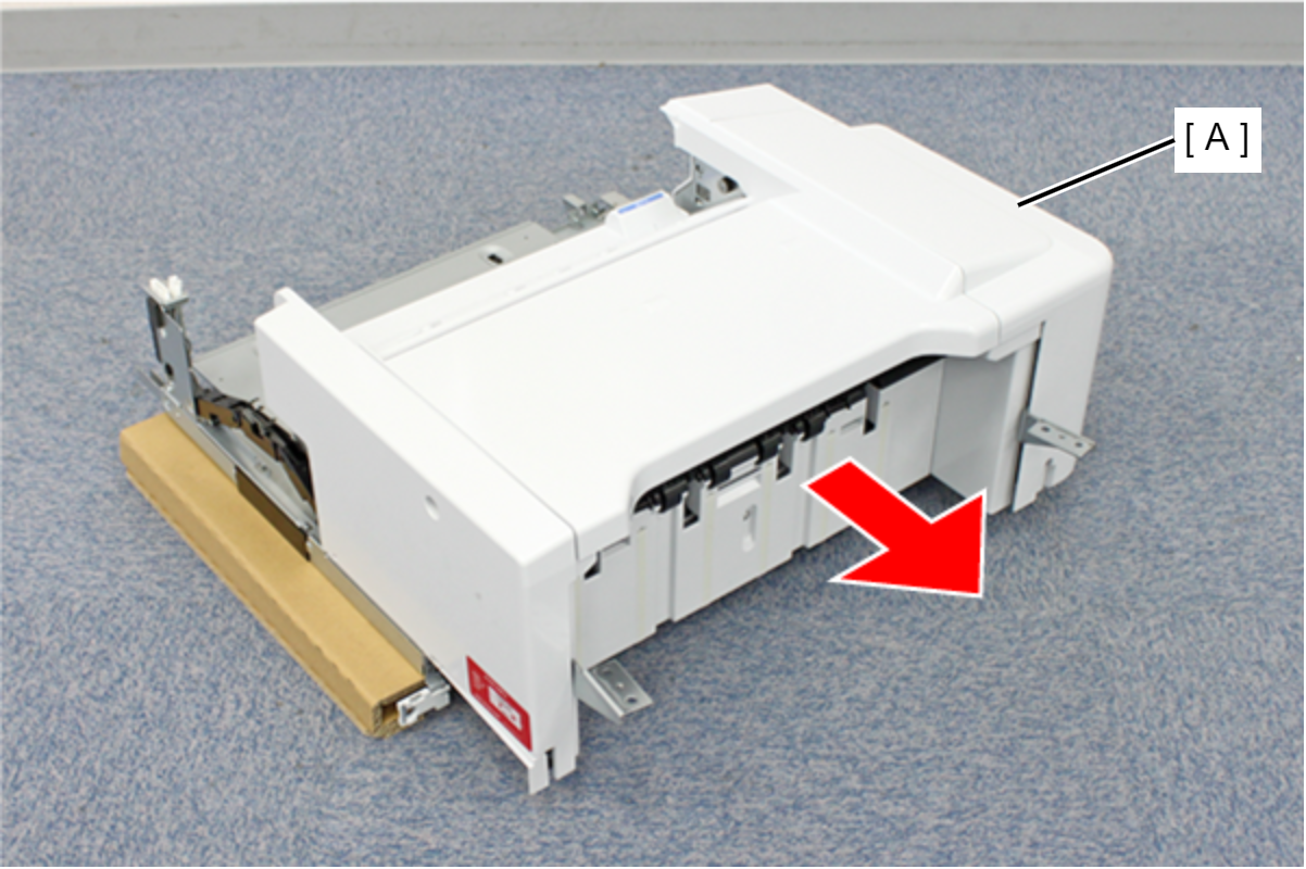
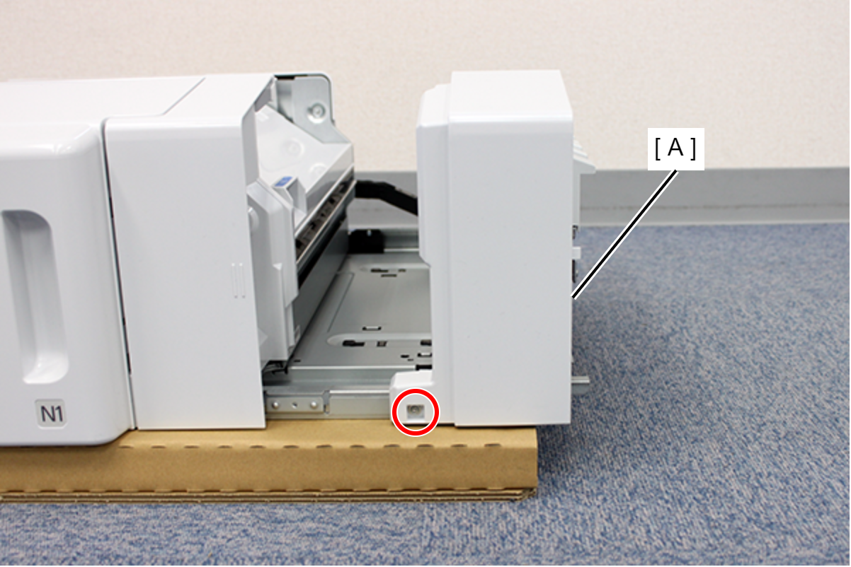
- Slide the inner finisher (A) in the direction of the arrow.
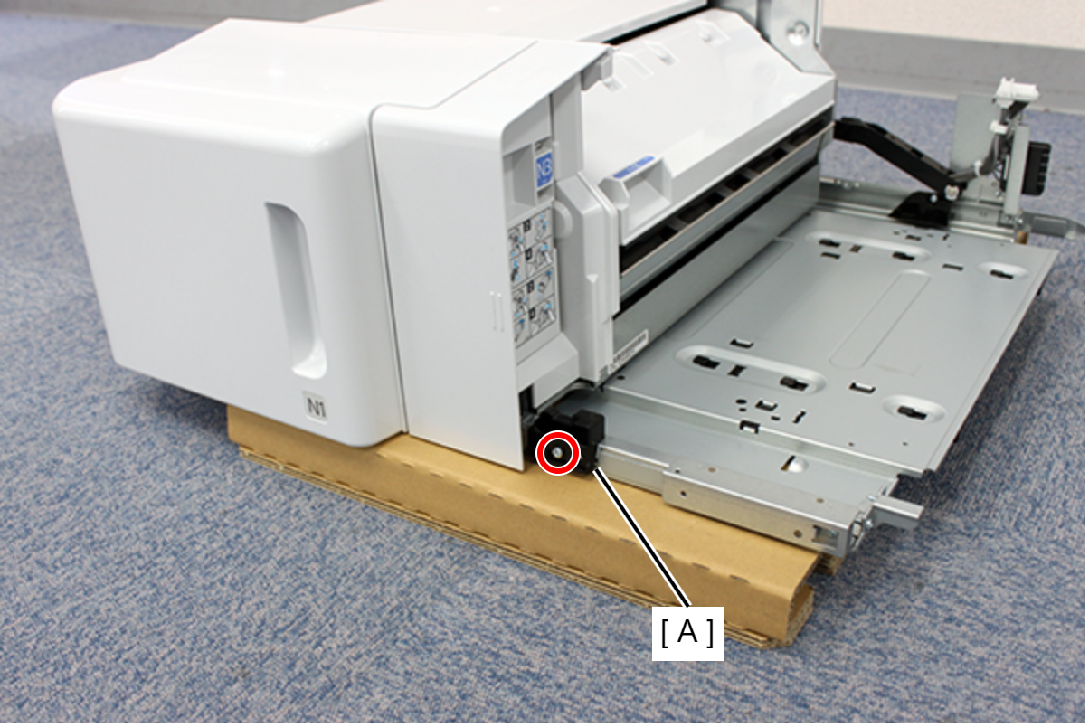
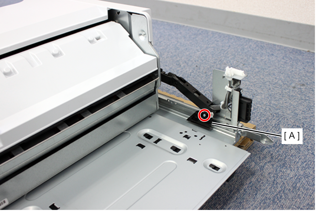
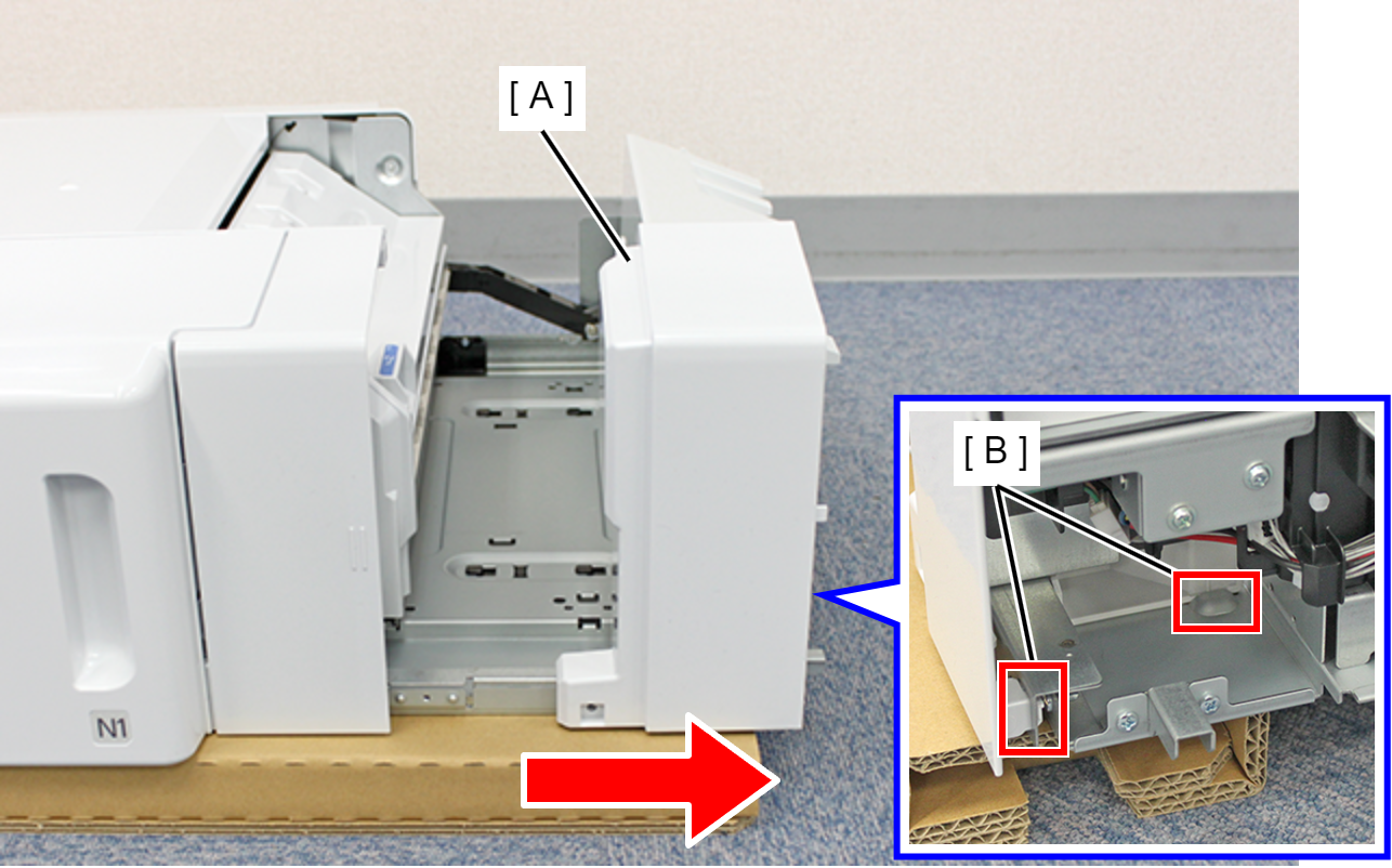
- Remove 1 screw and remove the Front Stopper (A).
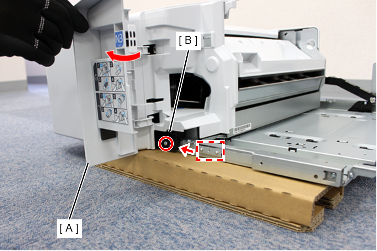
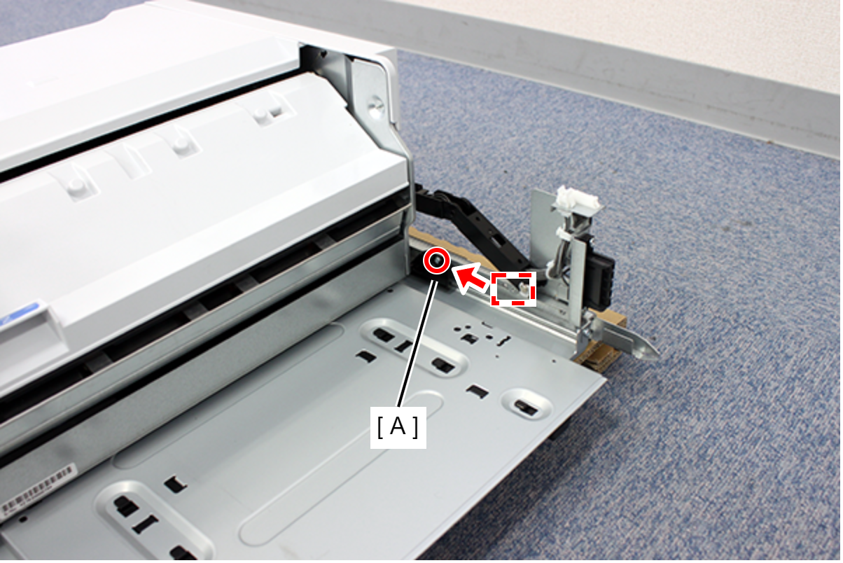
- Open the inner front cover (A), attach the front stopper (B) to the position shown in the illustration, and secure it with one screw.
- Remove 1 screw and remove the Rear Stopper (A).
- Install the rear stopper (A) in the position shown in the illustration, and secure it with 1 screw.
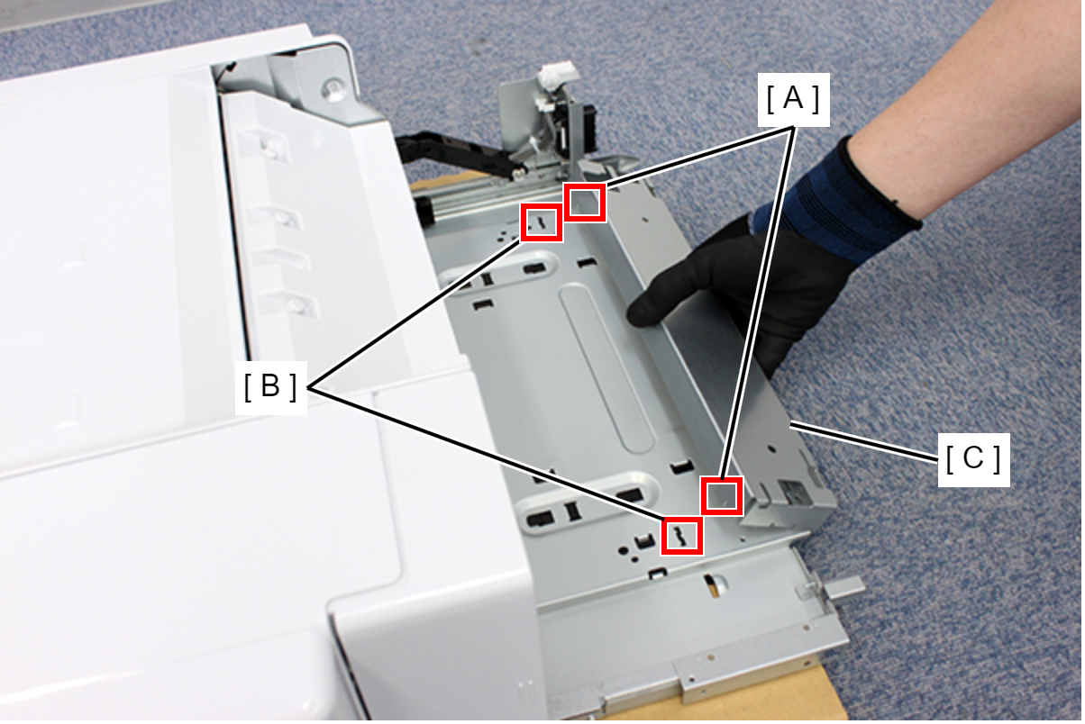
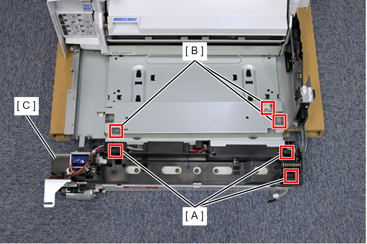
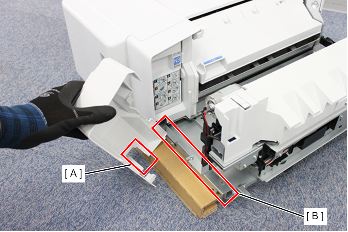
- Align the 2 protrusions (A) with the 2 holes (B) in the frame and attach the base frame (C).
- Secure the base frame (A) with 4 screws.
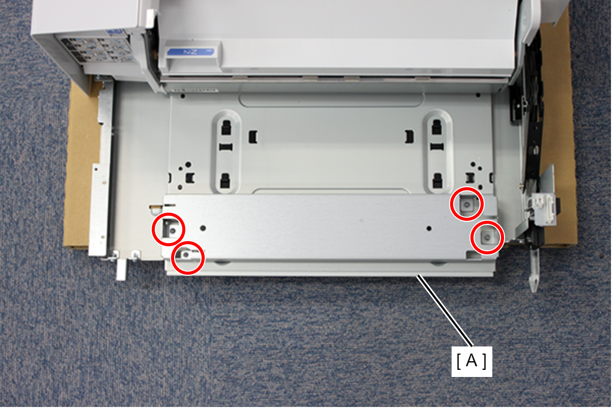
 : 3x8DC/P
- Align the three hooks (A) on the bottom of the punch unit with the 3 holes (B) on the base frame, and attach the punch unit (C).
- Slide the punch unit (A) in the direction of the arrow, and secure the punch unit with 3 hooks.
- Align the center line (A) of the scale with the center of the screw hole (B) and fix it with 1 screw.
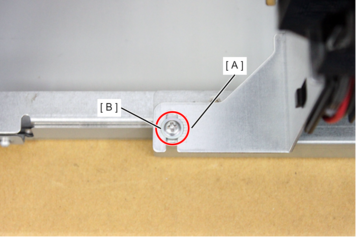
- : 3x8DC/P
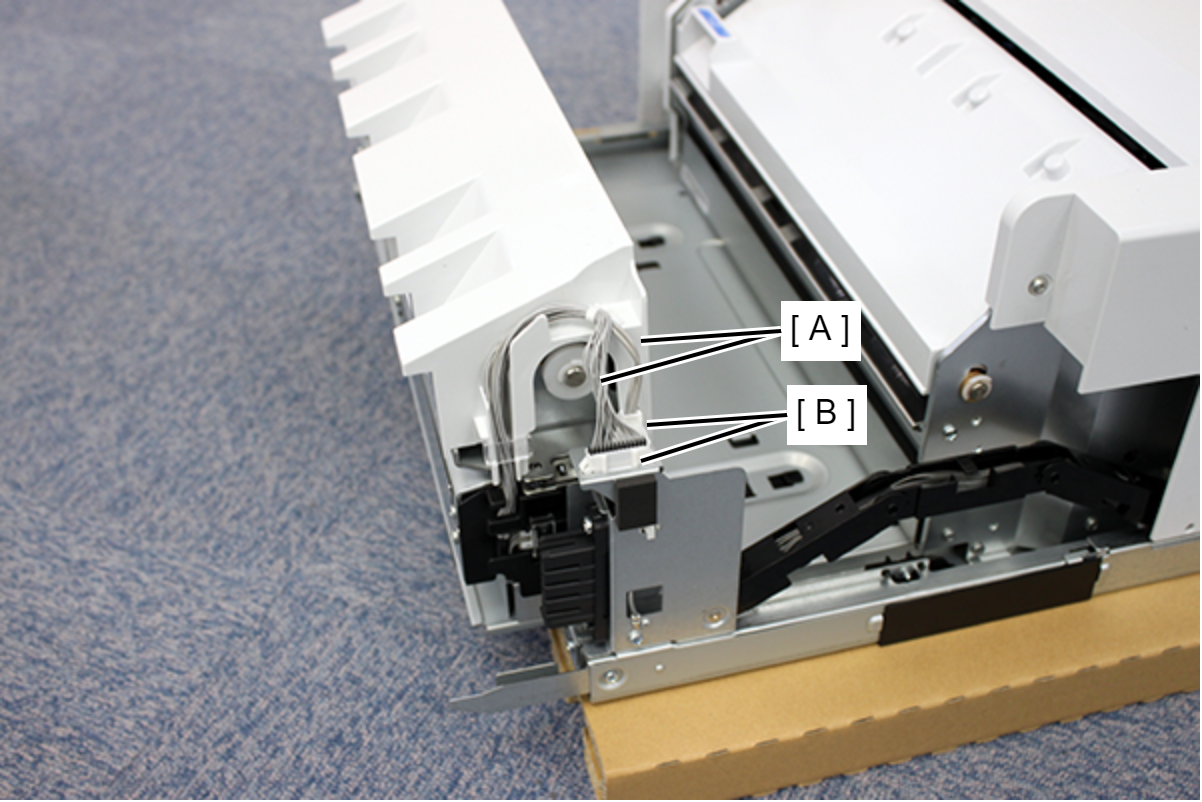
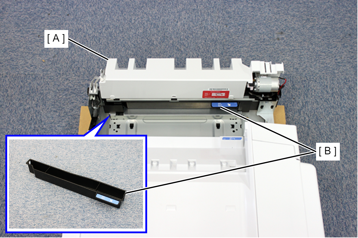
- Connect the 2 cables (A) of punch unit B to the 2 connectors (B).
- Attach the punch scrap tray (B) to the punch unit (A).
- Align the groove (A) of the inner front cover with the rail (B) of the inner finisher and attach it.
- Slide the inner front cover (A) in the direction of the arrow, align the 2 hooks with the 2 holes, and attach the inner front cover (B).
- Secure the inner front cover (A) with 1 screw.
- : 3x8DC/P
- For the subsequent steps, refer to the inner finisher installation procedure.
Inner Finisher Installation Procedure