Inner Finisher Installation Procedure
 Caution / 注意 Caution / 注意 |
Be sure to check the following precautions before installation.
|
 Check Point / チェックポイント Check Point / チェックポイント |
When using the Inner punch unit, install the Inner punch unit before installing the Inner finisher. |
Items to Prepare
- Bundled item of Inner Finisher
- Bundled Items of Inner Bridge Unit
- Phillips (+) screwdriver
Installation Procedure
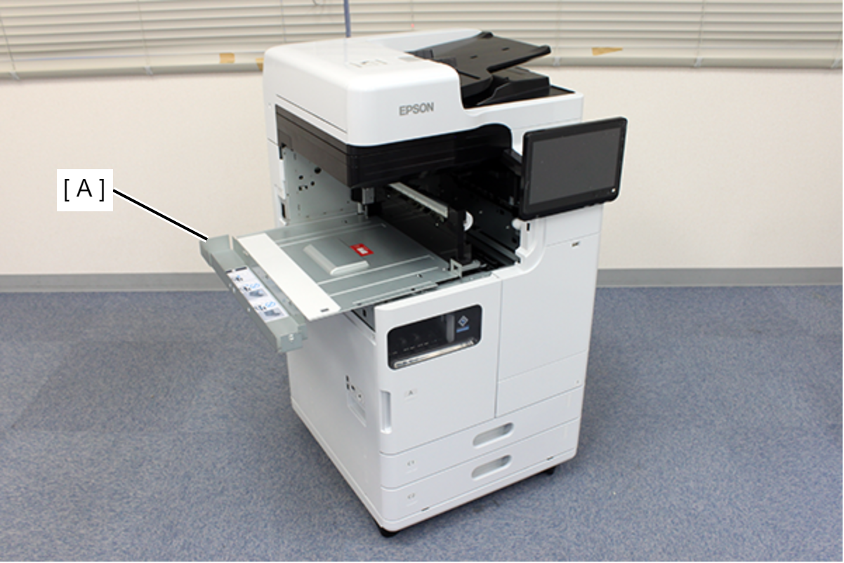
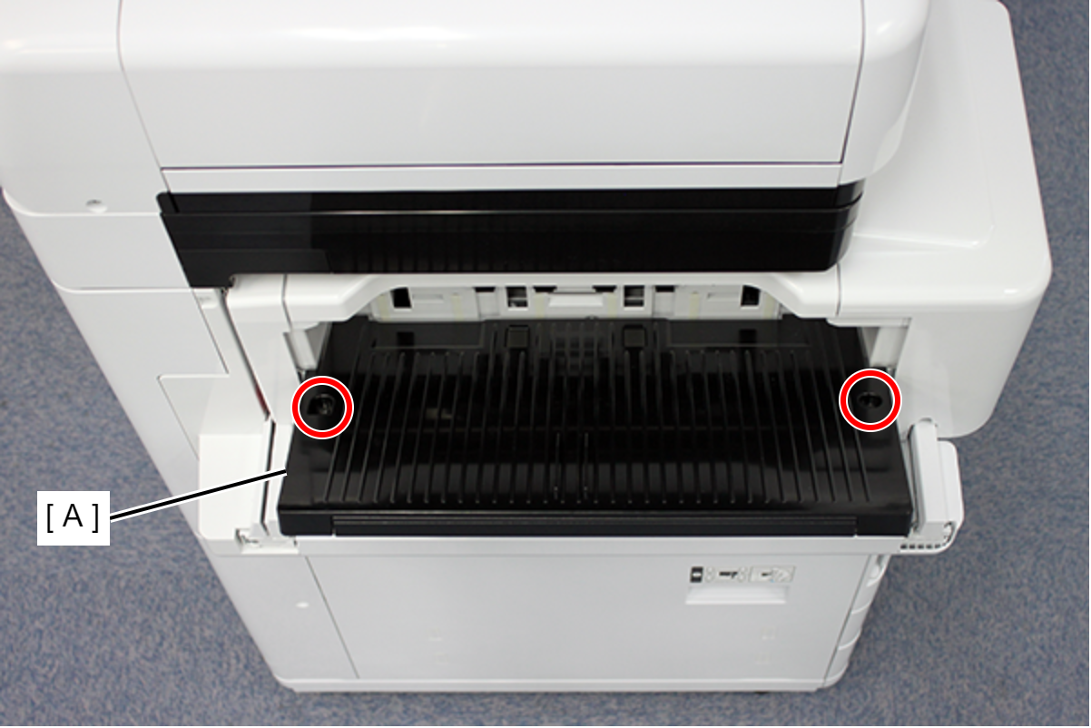
- Remove the 2 screws and remove the Front Left Cover (A). (S7:
 )
)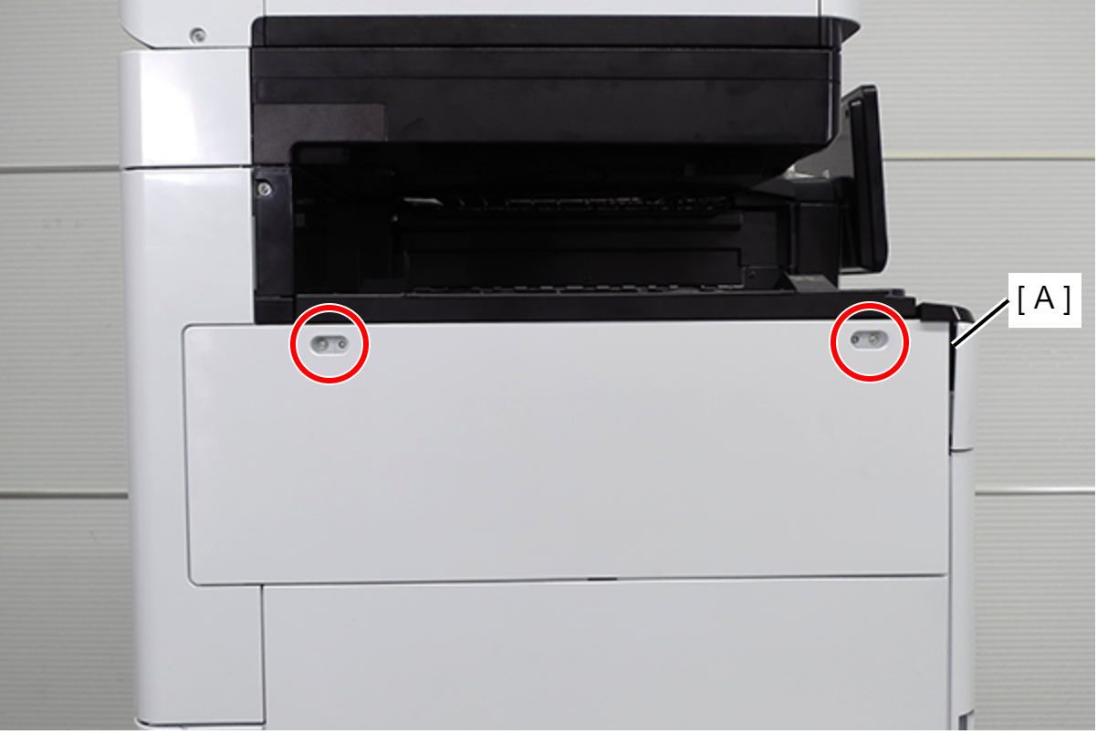
- S7: C.B.STITE(P4), SCREW, 3X10, F/ZN3C
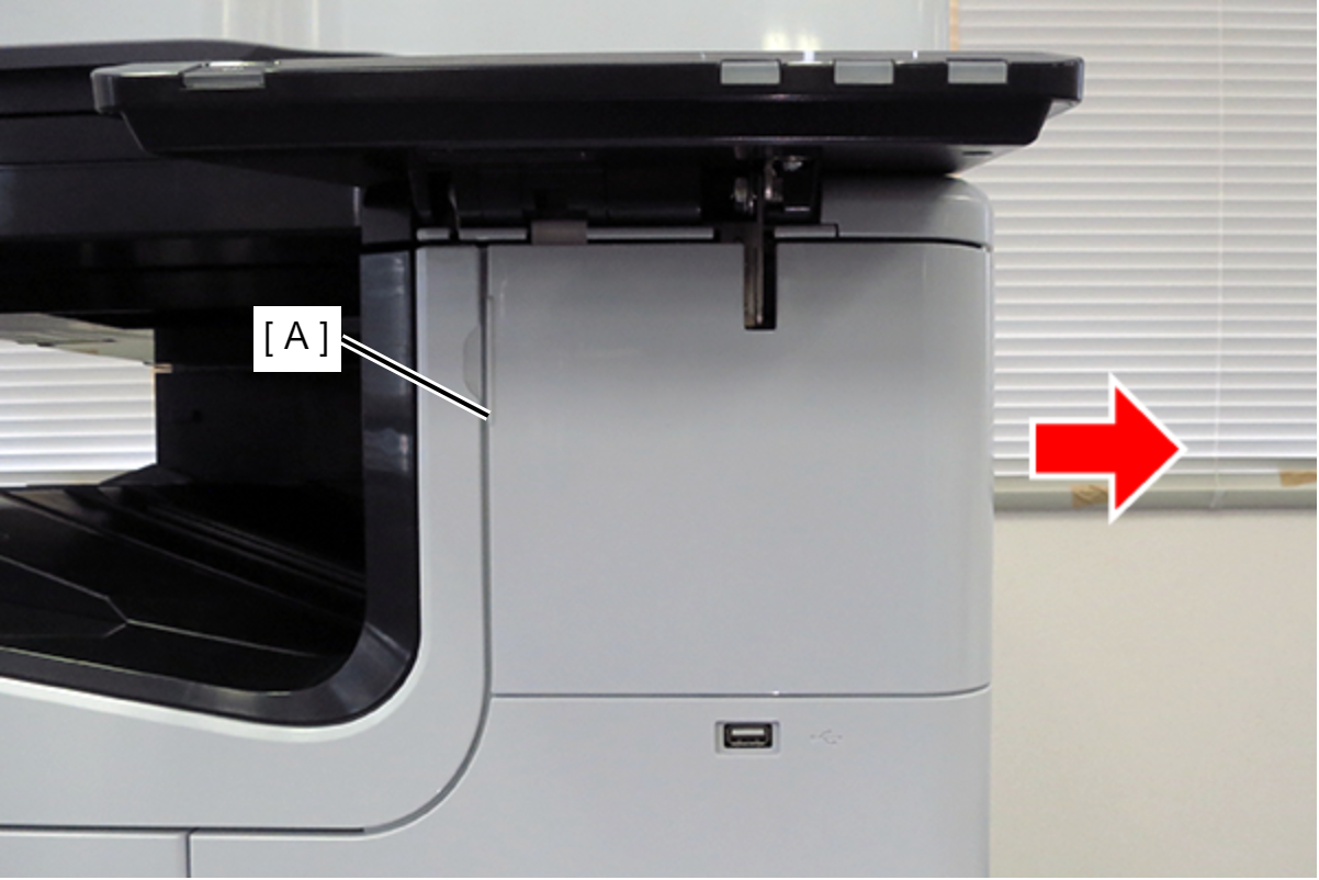
- Slide the front decorative cover upper (A) in the direction of the arrow to remove it.
- Remove one screw, and remove the front cover upper (A) in the direction of the arrow while pressing the hook. (S7:)
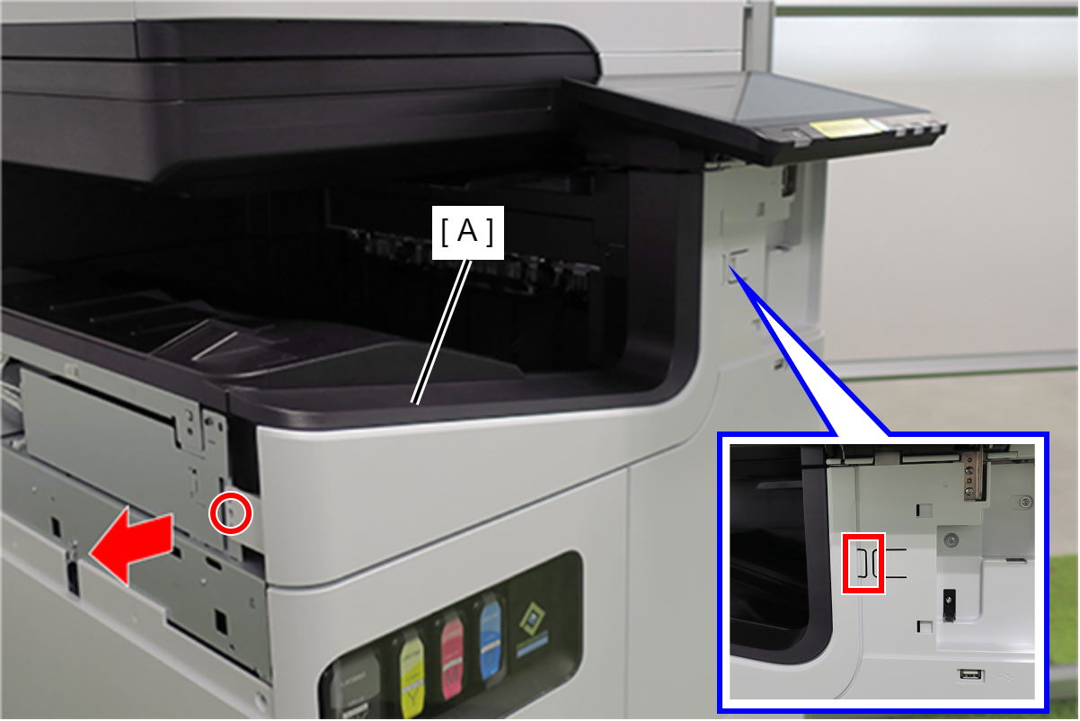
- S7: C.B.STITE(P4), SCREW, 3X10, F/ZN3C
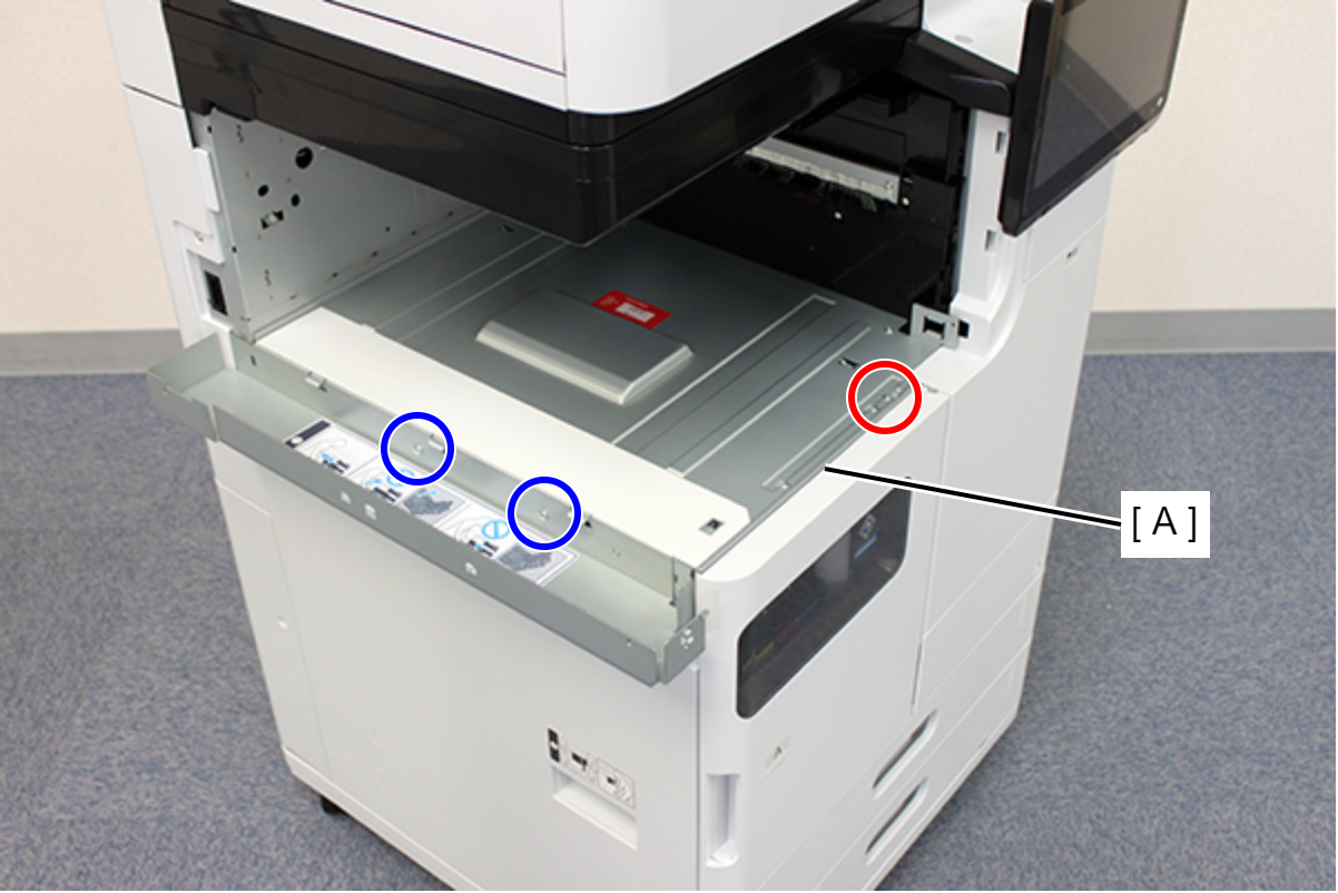
- Remove 1 screw and remove the Polyester file cover plate (A).
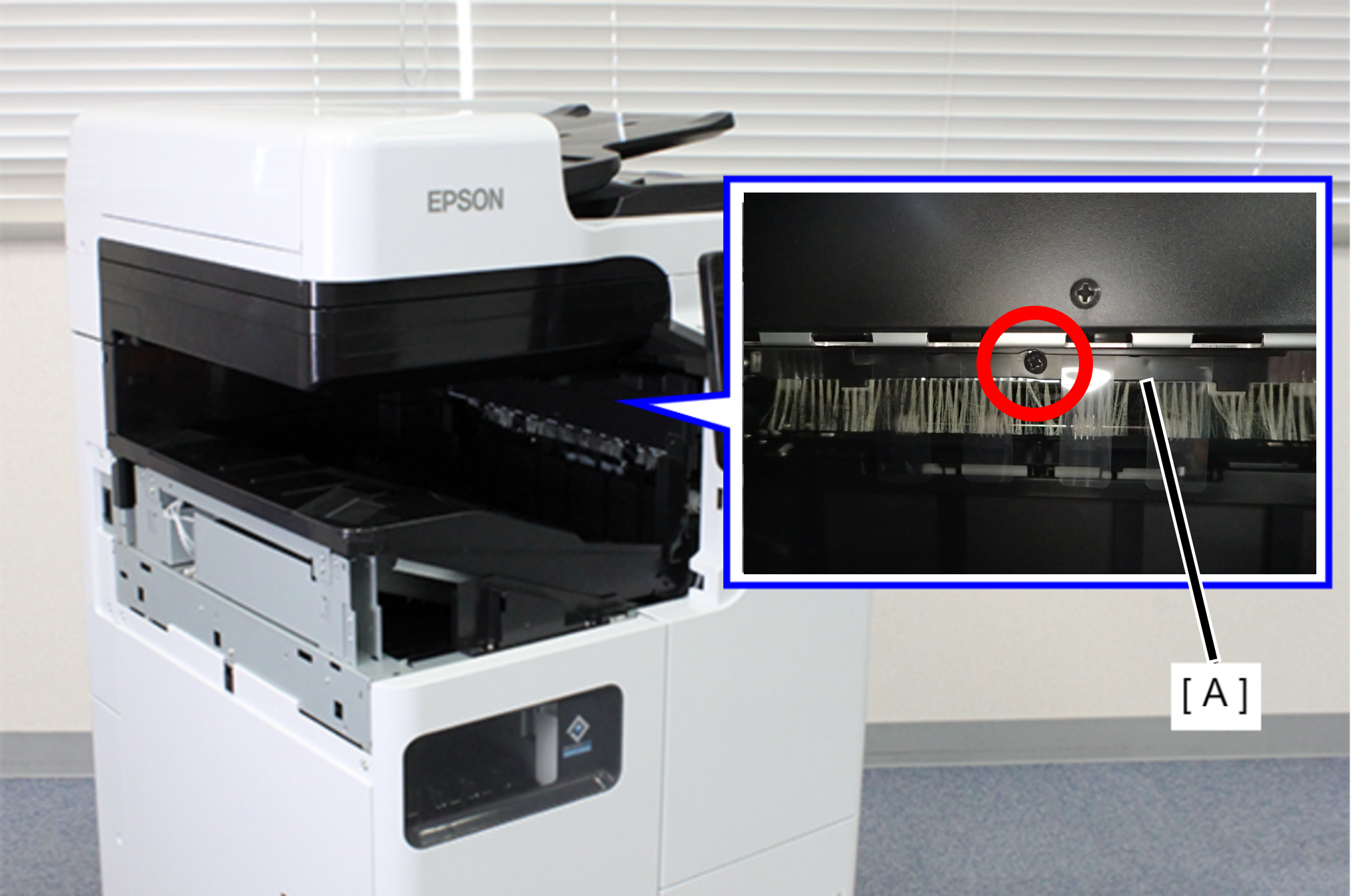
 :3x8D/BK/P
- Remove 1 screw and remove the FD Inner Cover Upper (A).

- : 3x8DW/P
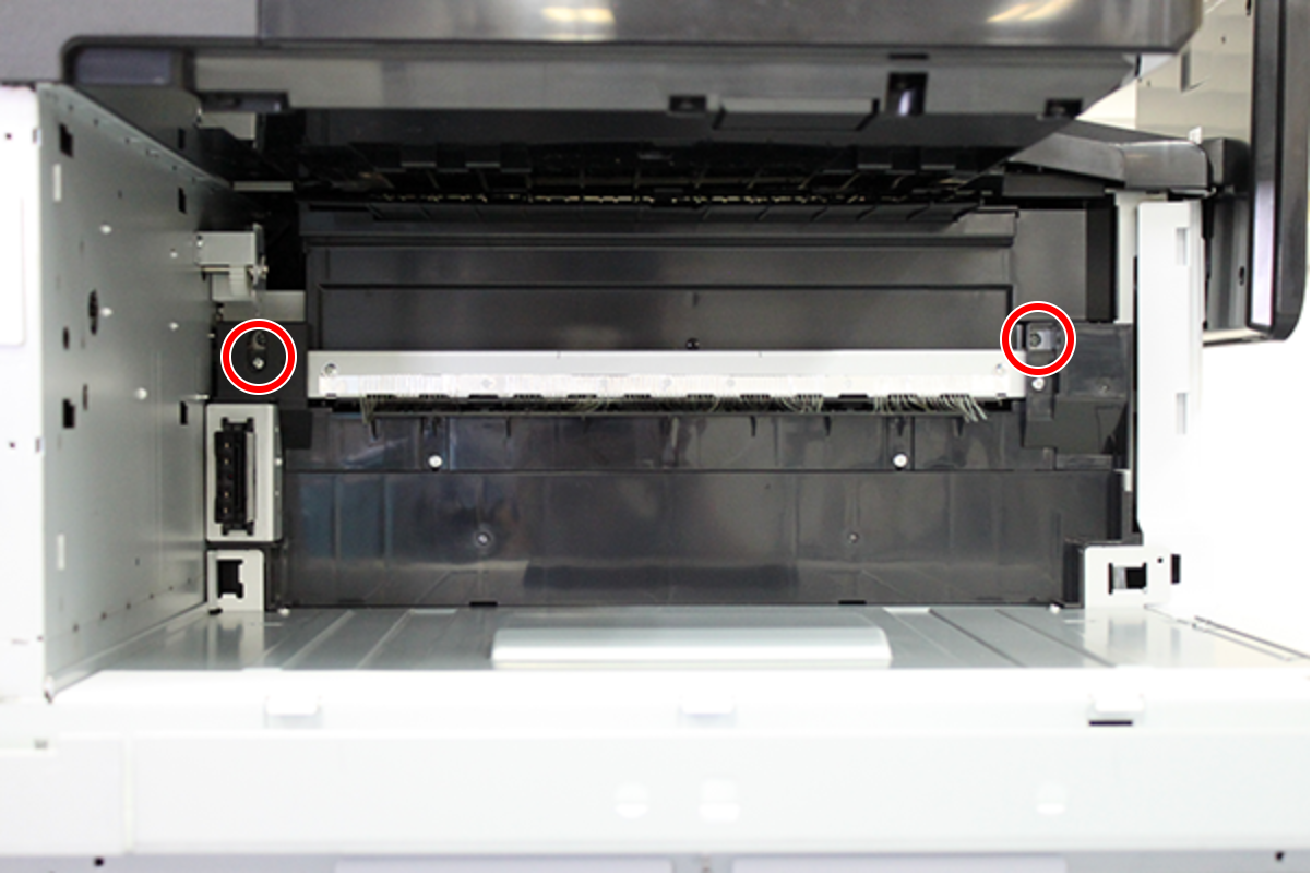
Remove the 2 screws that secure the Ejection paper sensor Assy (A).

- : 3x8D/BK
 Note / 補足
The Ejection paper sensor Assy will be removed in a later procedure.
- Remove the two cables (A) from the connectors.
- Lift the FD frame (A), release the two hooks, and remove it to the left side of the product.
- Remove the screw that secures the ground wire (A).
- : 3x8D/P
- Route the ground wire (A) around the guide.
- Remove the 4 screws that secure the FD Stacker Assy (A).

- : 3x8D/P
- Hold the position shown in the figure and remove the FD Stacker Assy (A).
- Remove the 2 screws and slide the 2 FD Stacker Assy mounting plates (A) in the direction of the arrow to remove them.
- : 3x8D/P
- Remove 1 screw and remove the FD inner cover bottom (A) in the direction of the arrow.

- : 3x8DW/P
- Remove 2 screws and remove the FD Stacker Guide (A). (S1:)
- S1: C.B.STITE R, SCREW, 3X8, F/ZN3C
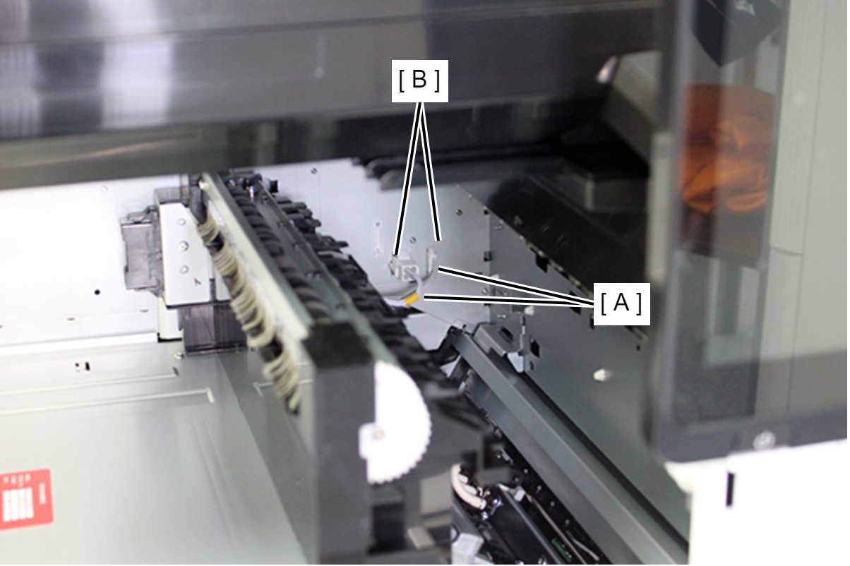
- Remove the cable from the connector (A), and slide the output detection sensor Assy (B) in the direction of the arrow to remove it.
- Pull the lever to open the Right Door Unit (A).
- Pull the lever to open the D3 Unit (A).
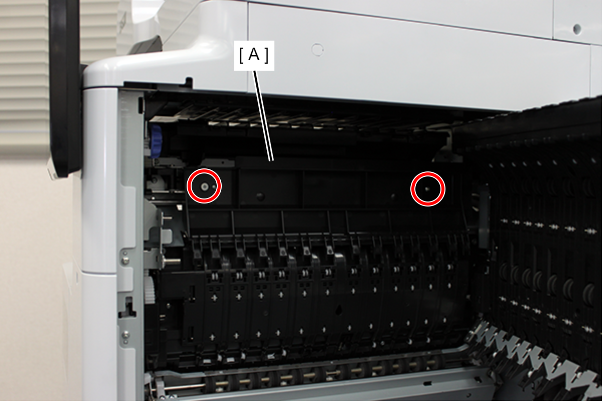
- Remove 2 screws and remove the Paper Guide (A).
- :3x5D/TBD
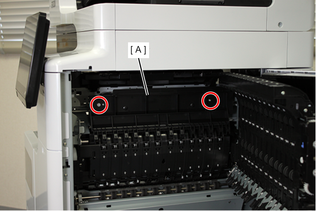
- Remove the 2 screws fixing the Driven Roller Assy.
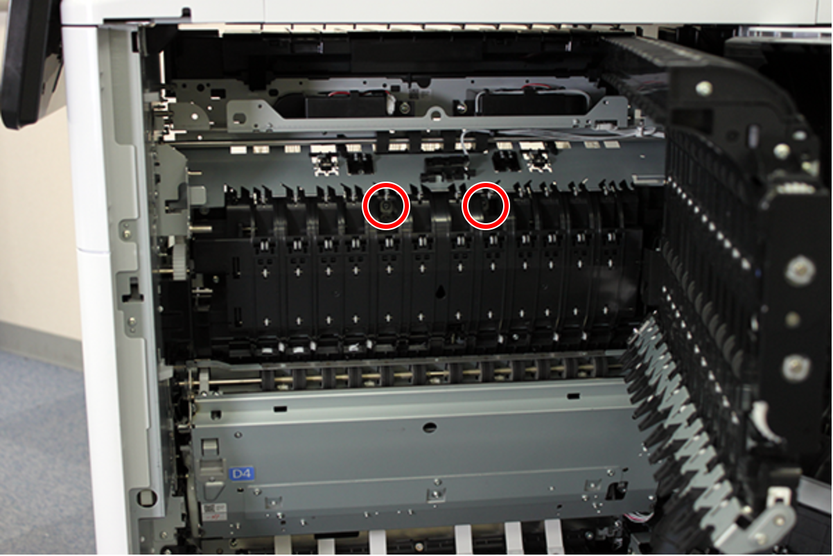
- : 3x8D/P
- Remove the Driven Roller Assy (A) by sliding it in the direction of the arrow.

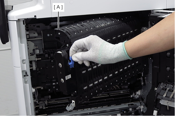
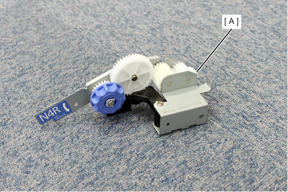
- Install the knob unit (A).
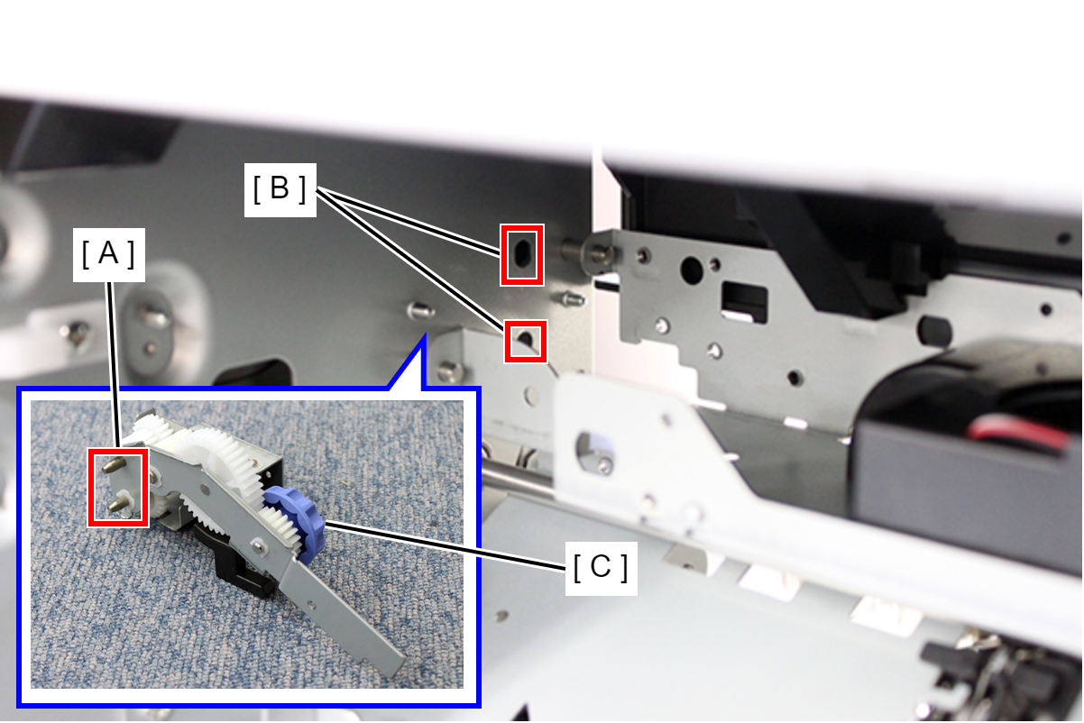
- Align the two positioning shafts (A) with the two holes (B) in the frame and attach the knob unit (C).
- Place the lever (A) on the cam (B).

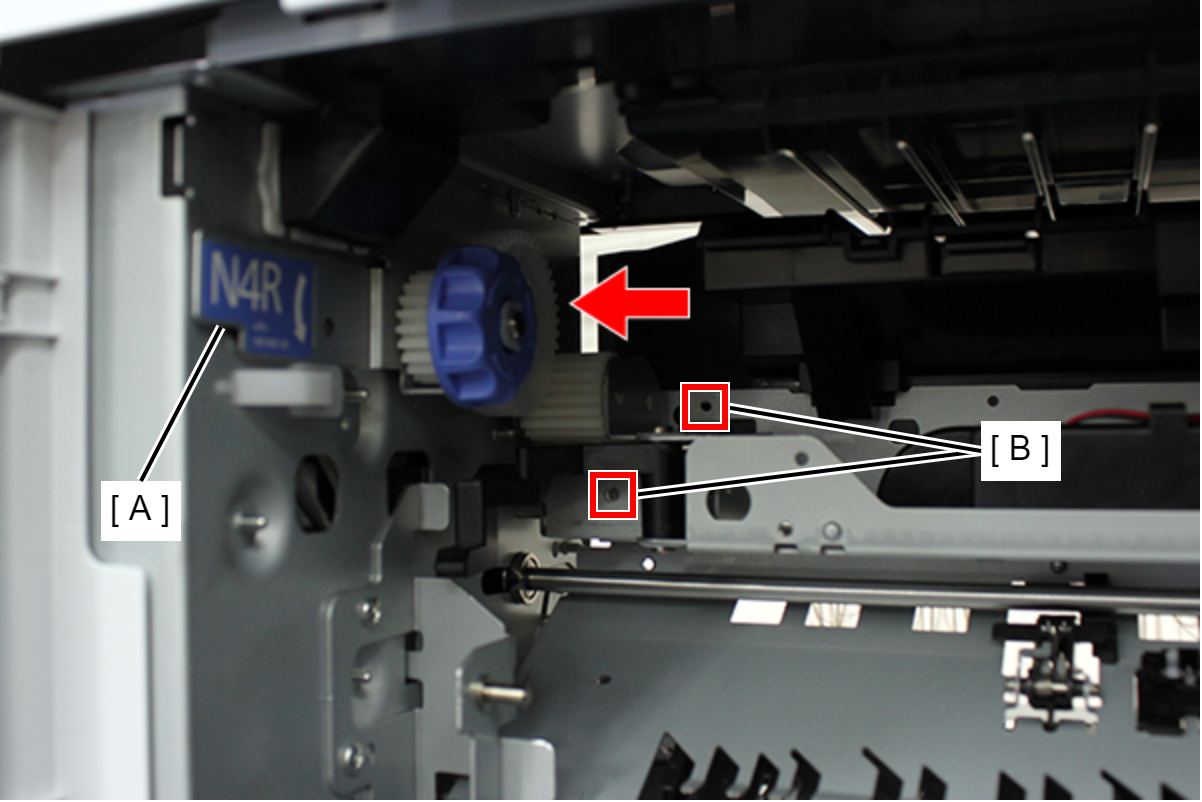
- Push the knob unit (A) in the direction of the arrow and align the two screw holes (B).
- Secure the knob unit (A) with three screws.

- : 3x4DNote / 補足
Use the fixing screws included with the bridge unit.
- Install the Paper guide (A) removed in step 19, and secure it with two screws.
- :3x5D/TBD
- Close the D3 unit and Right door unit.
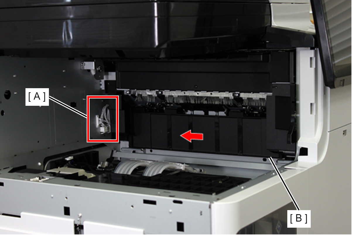
- Temporarily place the inner bridge (A) on the frame on the rear side of the main unit.
- Connect the two Inner bridge cables (A) to the connector (B) on the main unit.
Push the inner bridge (A) into the body.
Note / 補足If you can't push it into the main body, raise the right side (A) of the inner bridge slightly and insert it.
 Caution / 注意
If the inner bridge cannot be pushed all the way in, the tip of the inner bridge sheet metal may be deformed.
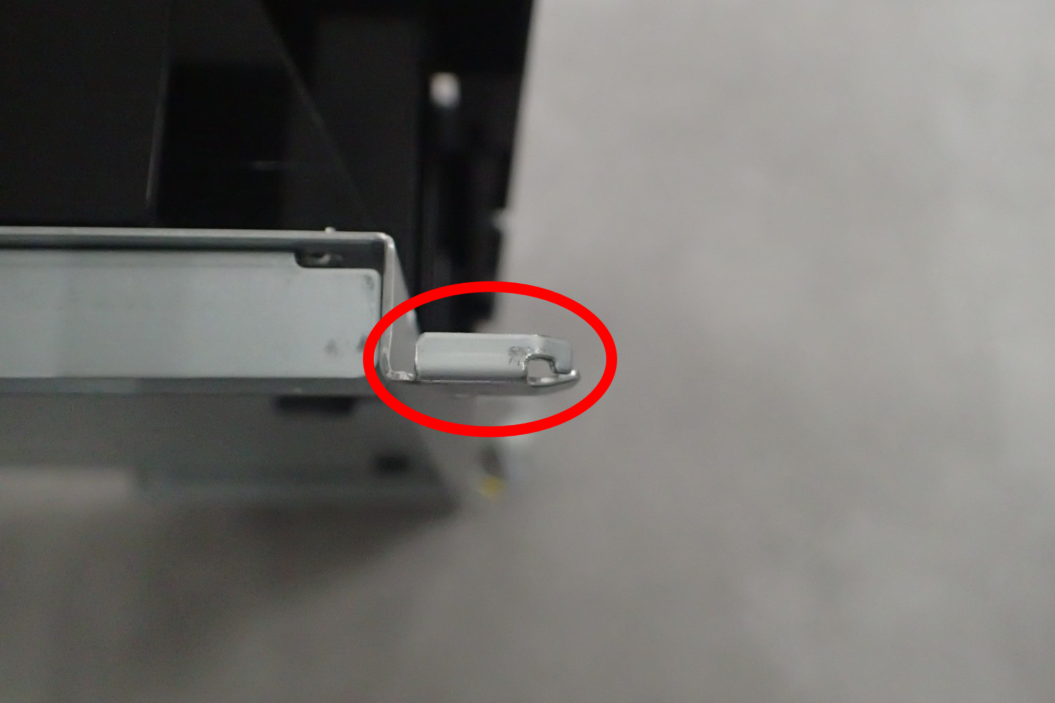
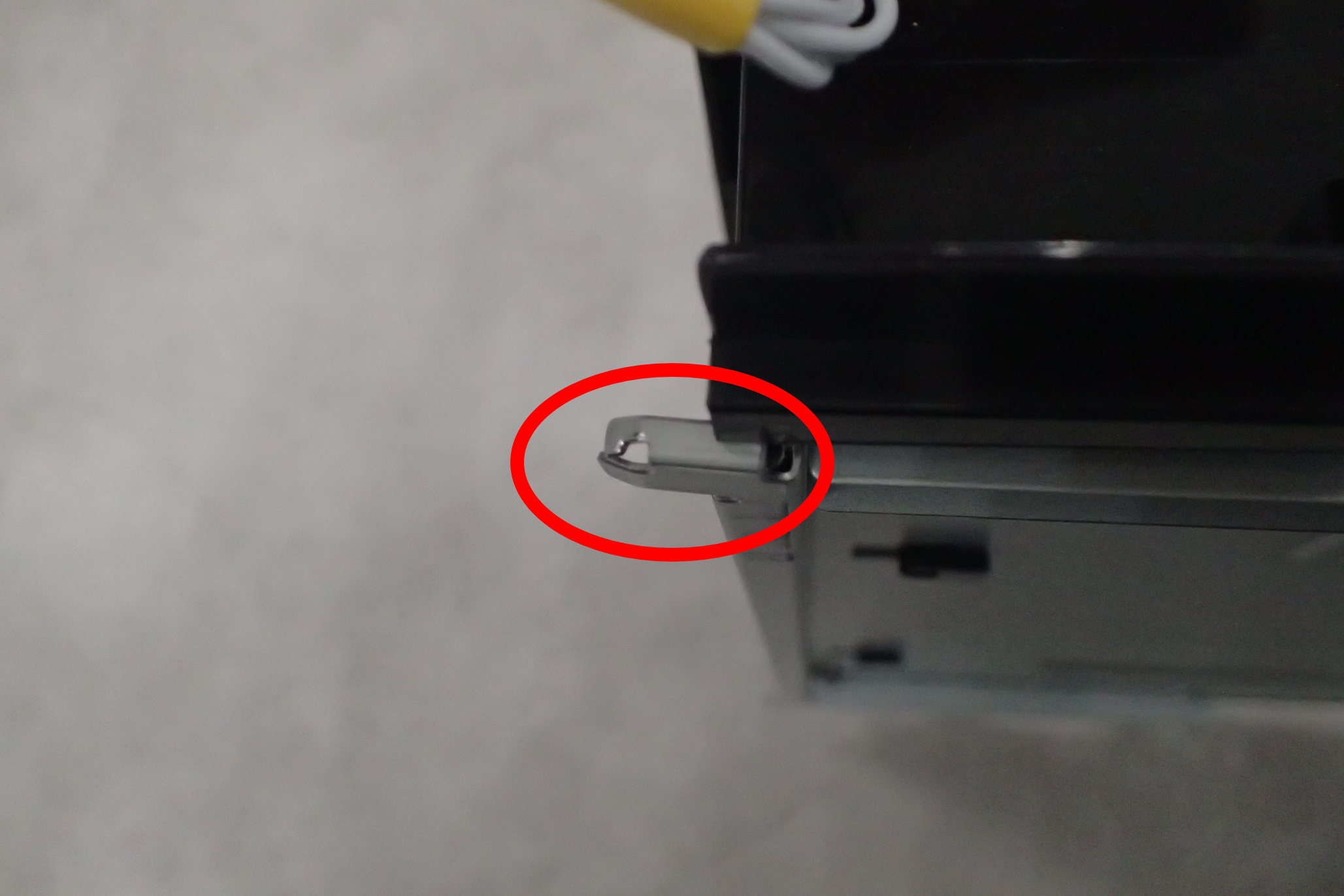
- While avoiding the protrusion (A) on the back of the inner bridge, raise the front side metal plate (B) about 10 mm and push it into the body.

 Note / 補足
Confirm that the two dowels (A) on the front side of the inner bridge are inserted.

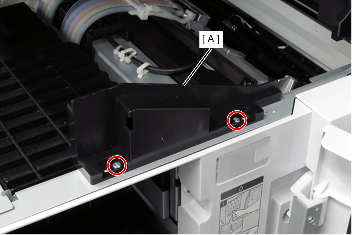
- Secure the Inner bridge (A) with five screws.
- : 3x8D/P
 : 4x8D/P
- : 3x8D/P
- Attach exterior parts 1,2,3.
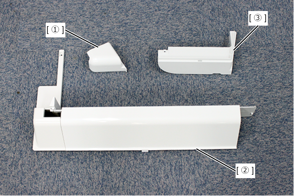
- Align the 2 dowels (A) of the exterior part 1 with the 2 holes (B) in the frame and the ribs (C) with the hooks (D) to attach the exterior part 1.

- While supporting exterior part 1, attach exterior part 2.
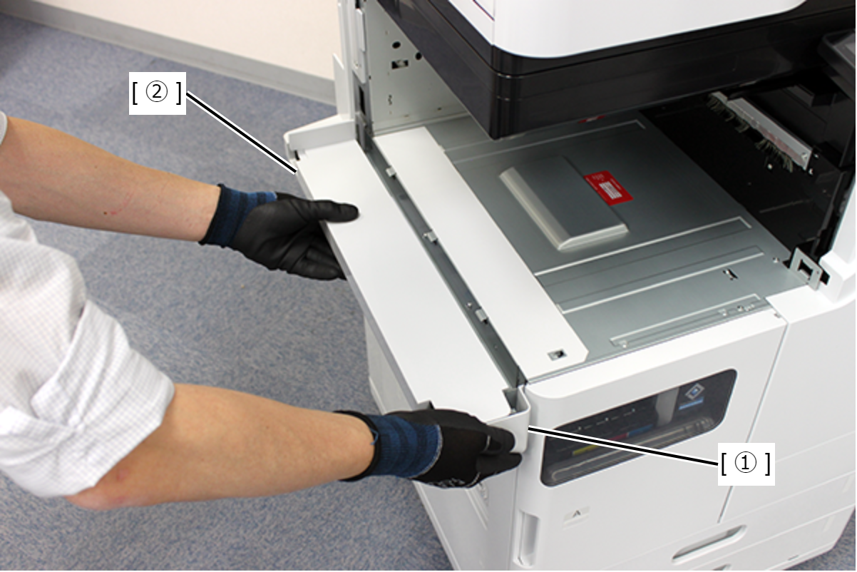
- Check that there are no floats at the joints of the parts 1,2.
- Fix exterior part 2 with one screw.

- : 3x8xD/P
- Align the two hooks (A) and the two holes (B), and attach the external part 3.
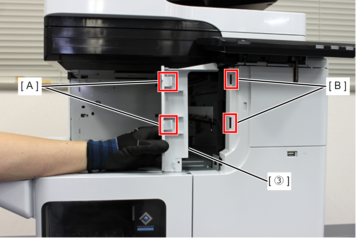
- Fix exterior part 3 with one screw.
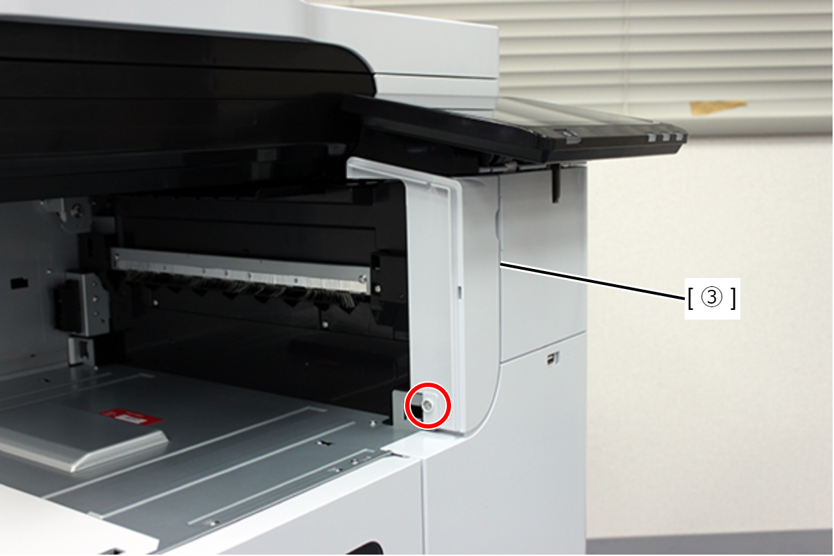
- : 3x8xD/P
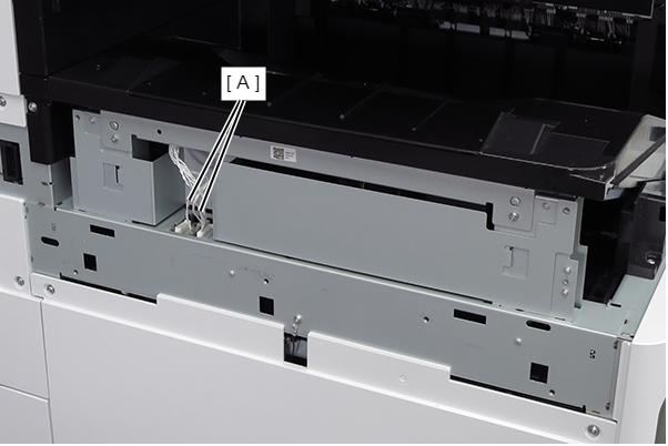
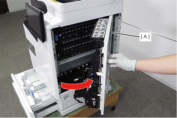
- Place the Inner finisher (A) on the Main Unit and slide it all the way to attach it.
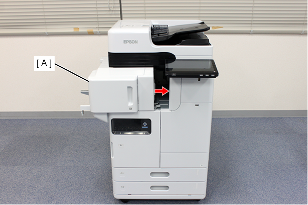
- Lock the casters (if an additional cassette or caster table is installed).
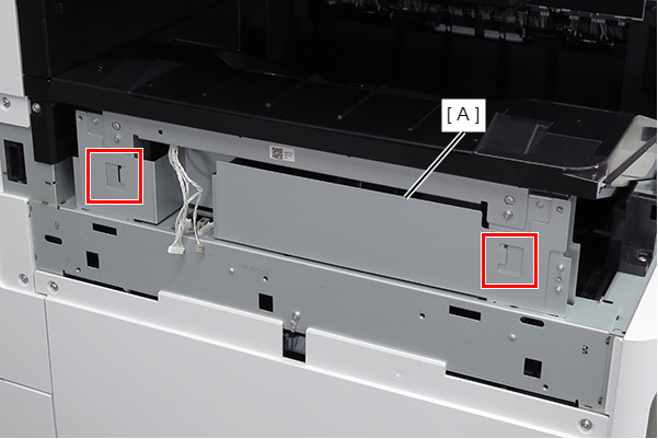
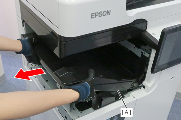
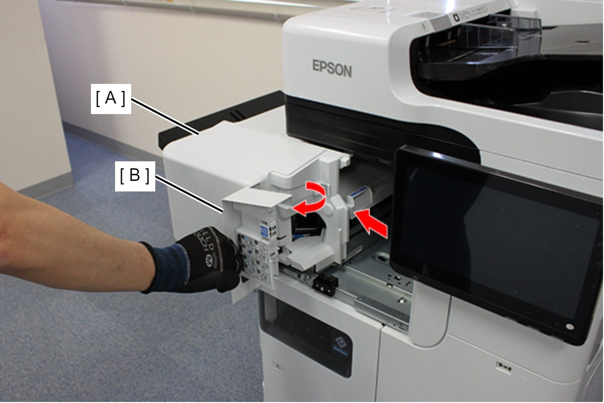
- Hold the red square part and push in the inner finisher (A).

 Note / 補足
This procedure must be performed under the following conditions.
- The printer is not moving.
- The inner finisher is pushed all the way in and not pulled out.
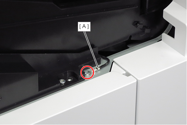
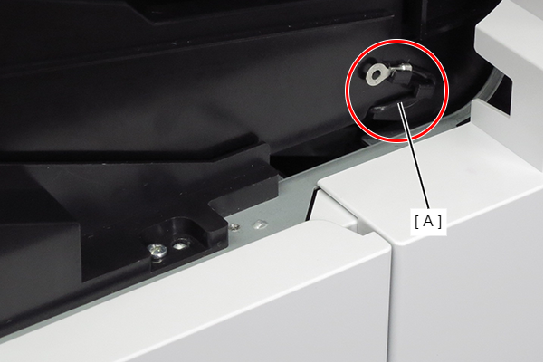
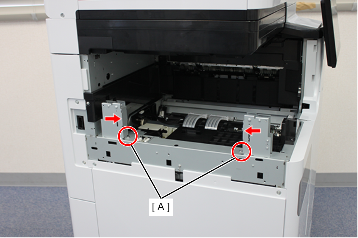
- Secure the Inner finisher (A) with two screws.
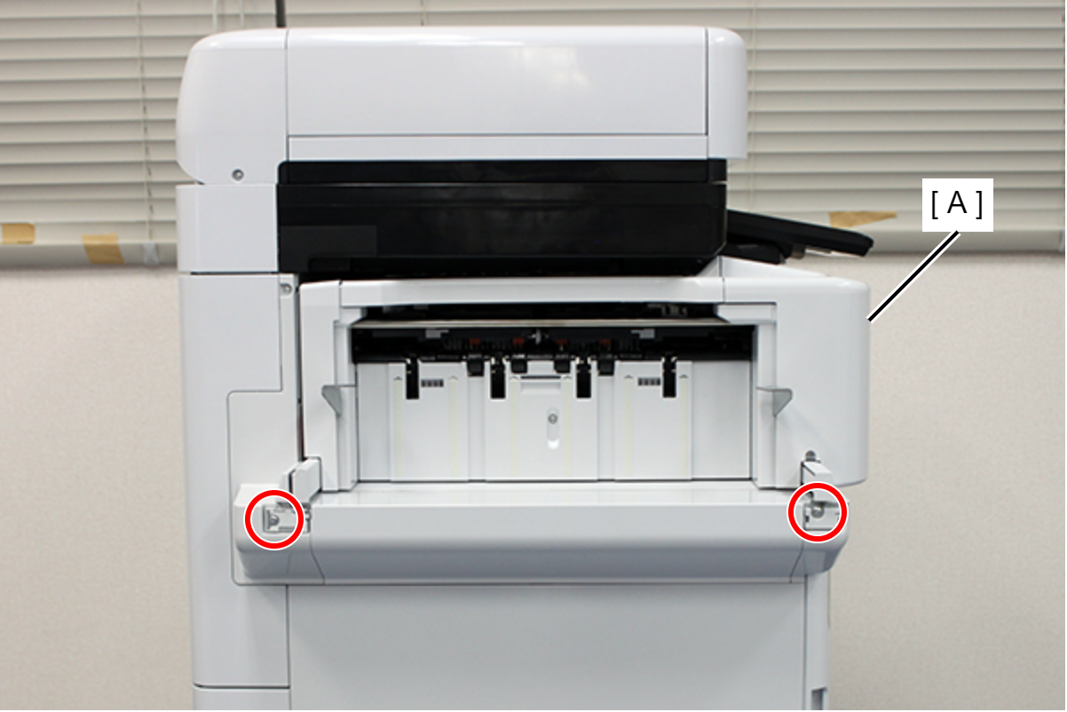
- : 4x8D
- Align the 4 dowels (A) with the holes and attach the finisher tray (B).

- Secure the finisher tray (A) with 2 screws.
- : 4x8DC/BK/P
- Pull out the inner finisher (A) and open the inner front cover (B).
- Insert the staple cartridge (A) into the staple unit (B).

- Close the inner front cover (A) and push the inner finisher (B) all the way in.
