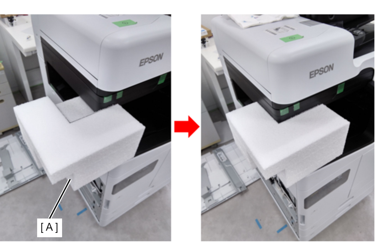
Protecting the products to avoid damages while transporting
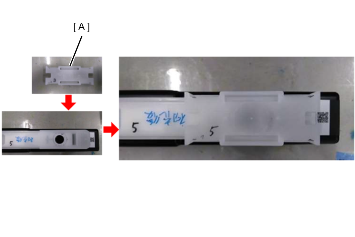
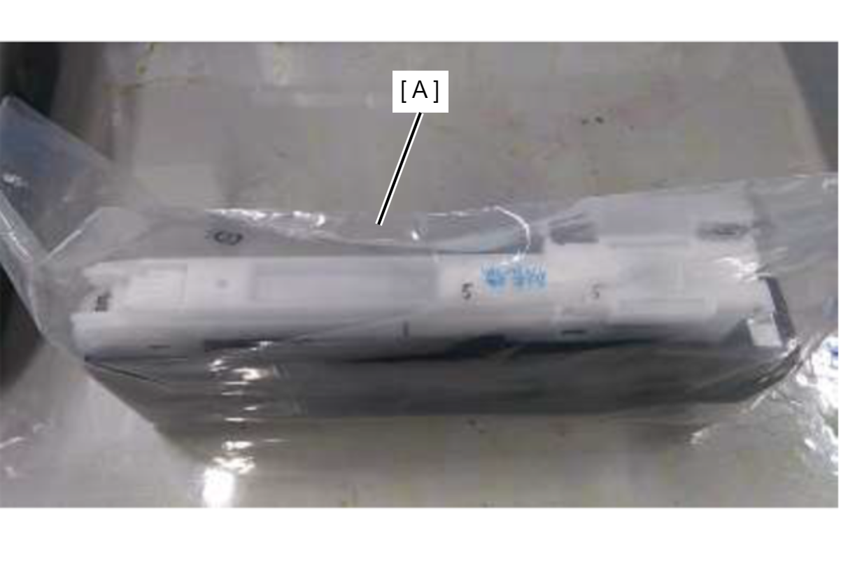
Ink cartridge
| Protection Point | Description |
|---|---|
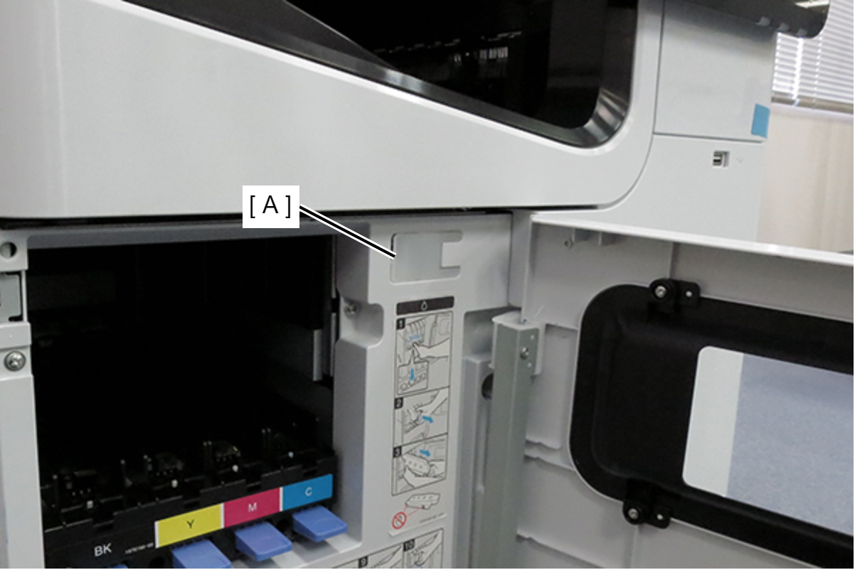
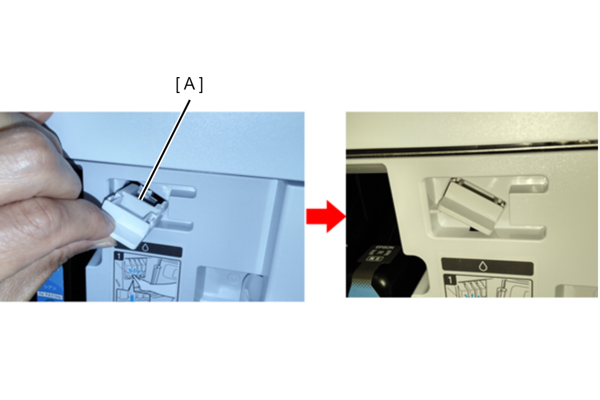
| Prevention of ink transfer during transportation
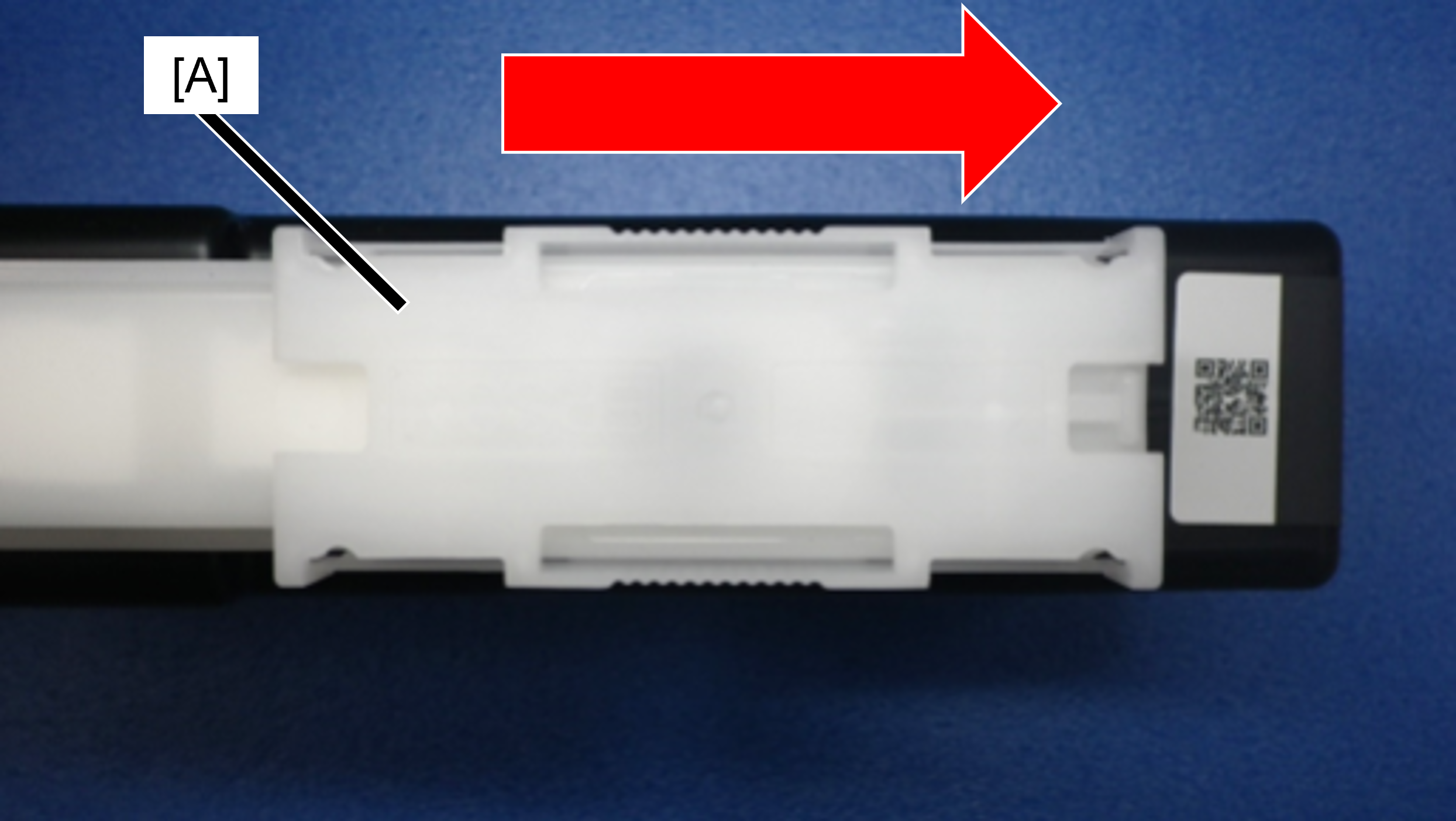
How to attach the ink supply port cap Slide the ink supply port cap (A) in the direction of the arrow until it clicks. The shape of the ink supply port cap is bilaterally symmetrical, so it can be installed in either direction.
|
|
Main Unit
In D4 Cover
 Caution / 注意 Caution / 注意 |
To prevent contact with the Belt surface during work, be sure to perform the items listed in the table in order from the top. |
| Protection Point | Description |
|---|---|
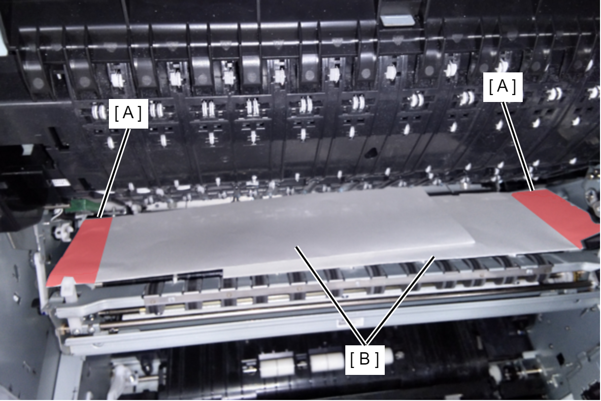
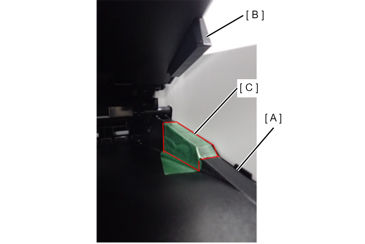
| Prevents rubbing of belt and belt gap regulating surface (A) due to vibration during transportation
|
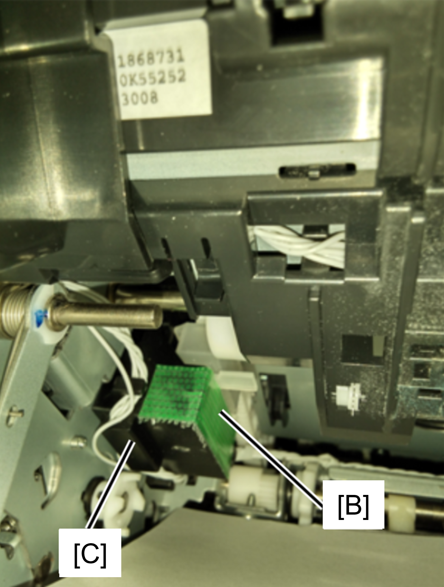
| Prevents the lift gear from coming off the cap unit due to vibration during transportation
|
| |
| Prevention of right door bearing axis bending
|


In A Cover
| Protection Point | Description |
|---|---|
| Prevention of Head unit lifting gear disengagement
|
|
Front
| Protection Point | Description |
|---|---|
| A cover opening prevention
|
| Cassette tray pop-out prevention
|
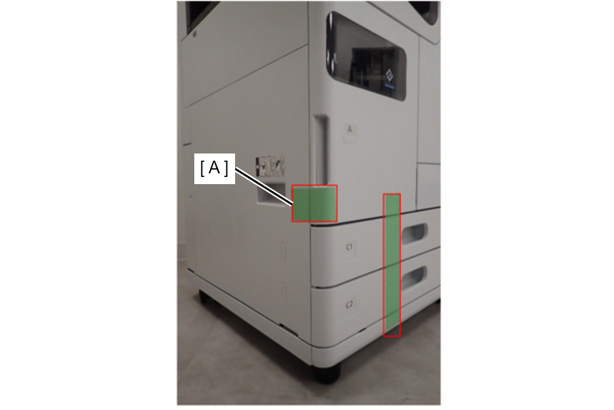
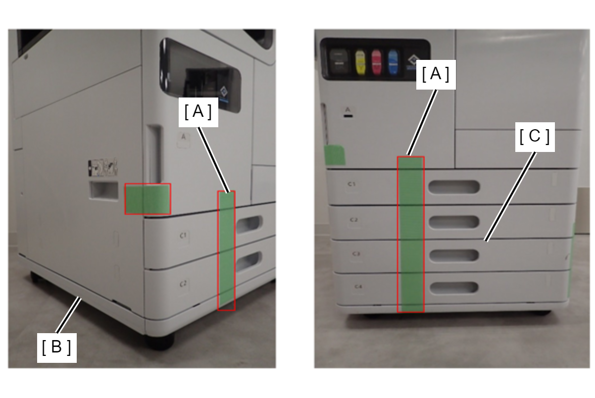
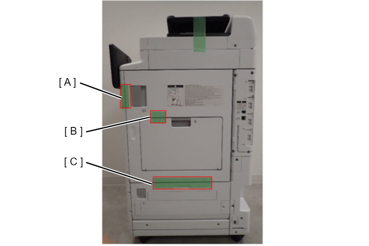
Right side
| Protection Point | Description |
|---|---|
| D1 cover/B cover/E cover opening prevention
|
ADF/SCN
| Protection Point | Description |
|---|---|
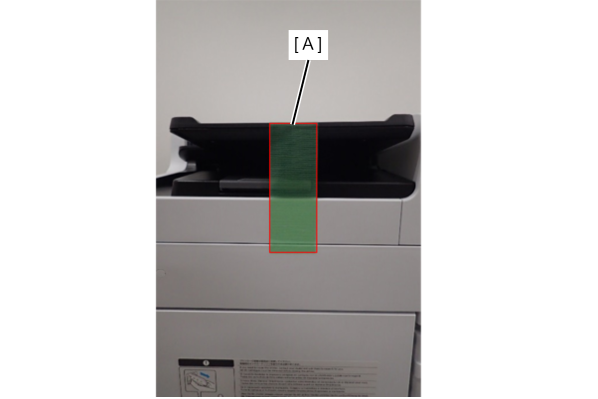
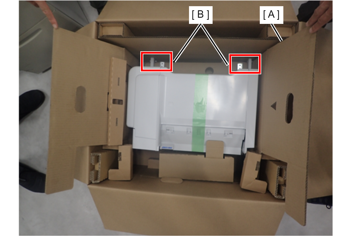
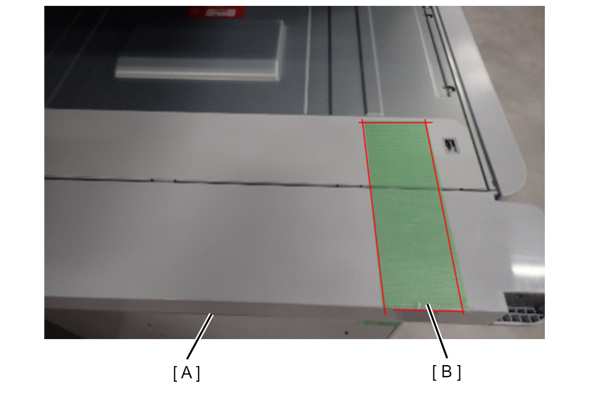
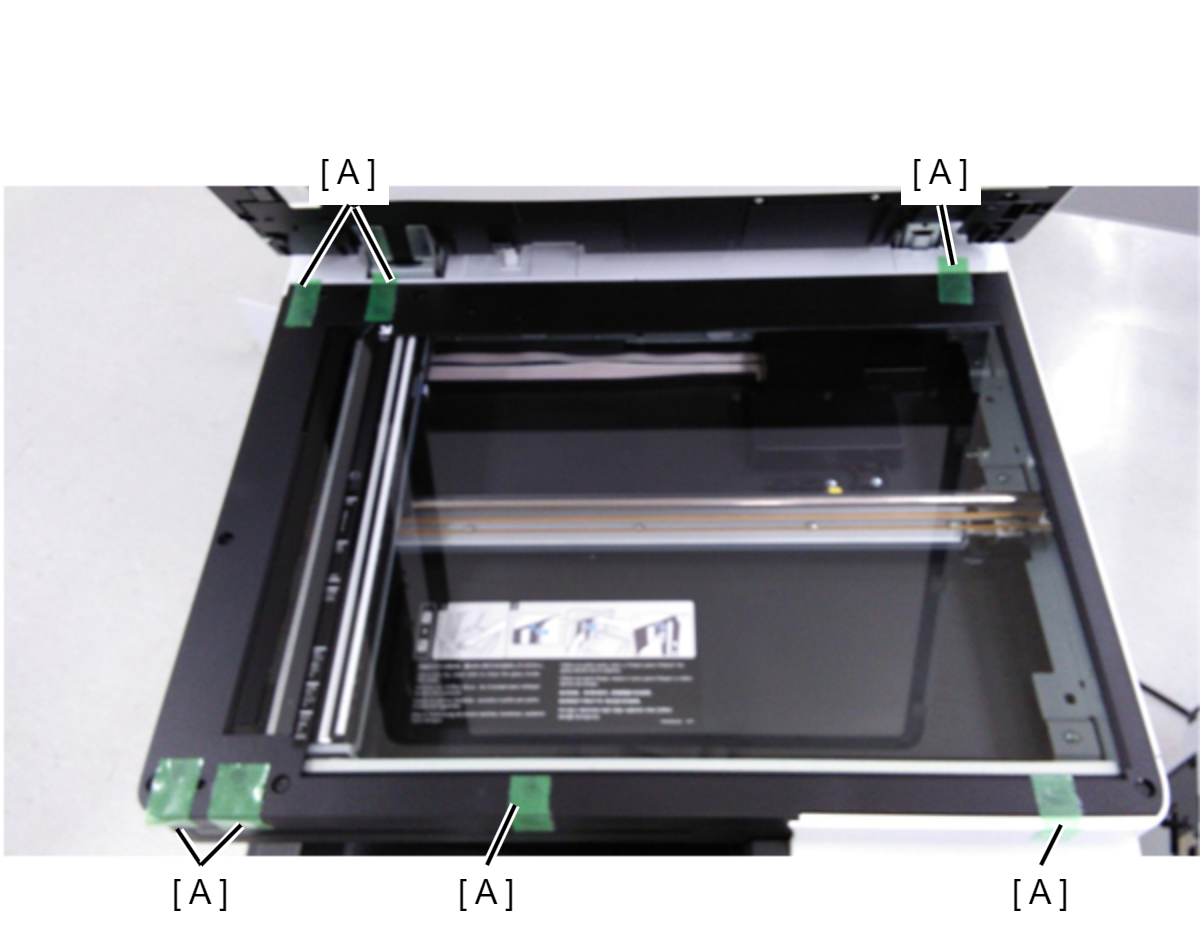 c91p_m1022cd.png | Preventing rubbing at the contact point between the flatbed of the SCN unit and the ADF unit
|
| Prevents contact surface abrasion between the ADF tray and ADF output tray
|
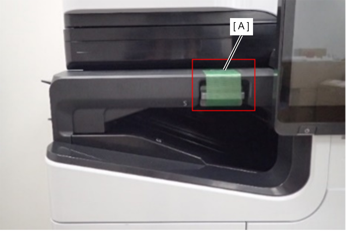
| Preventing the ADF document tray from flapping
|
No eject option parts installed
| Protection Point | Description |
|---|---|
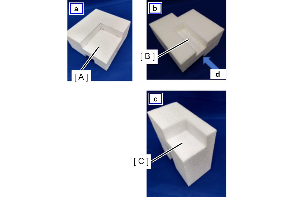
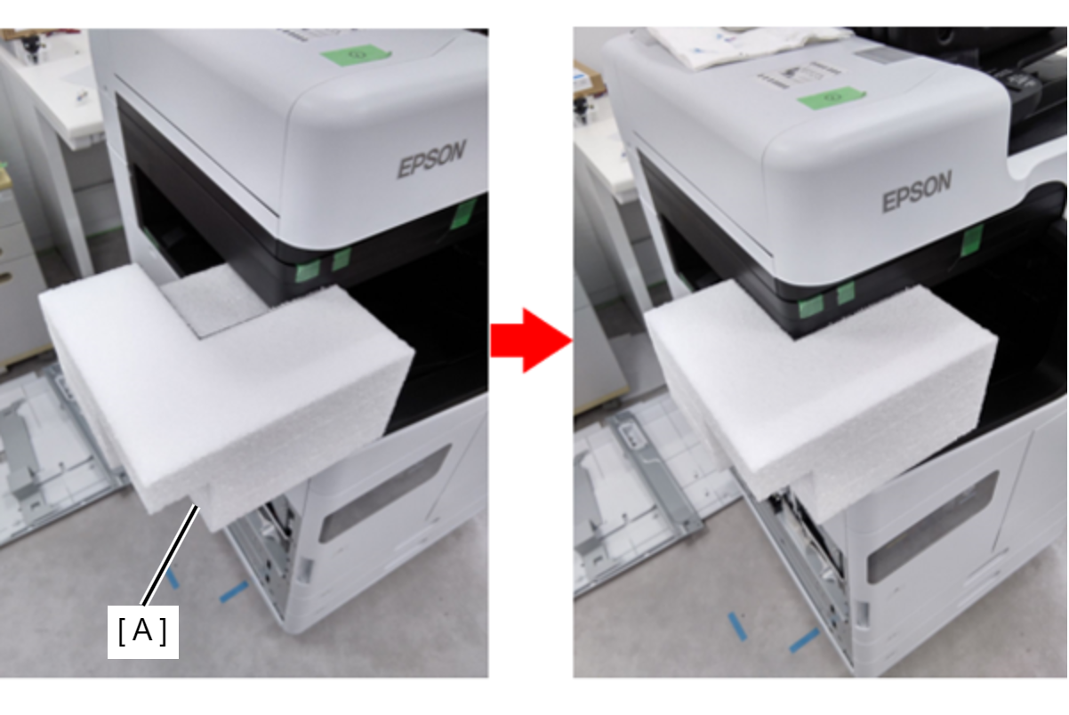
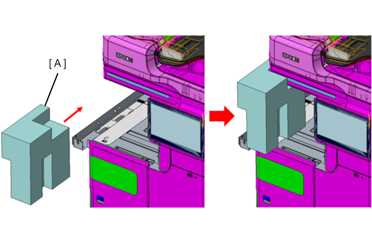
| ADF/SCN Unit fall prevention <Shape of ADF/SCN support part> ----
|
|
Floor finisher
| Protection Point | Description |
|---|---|
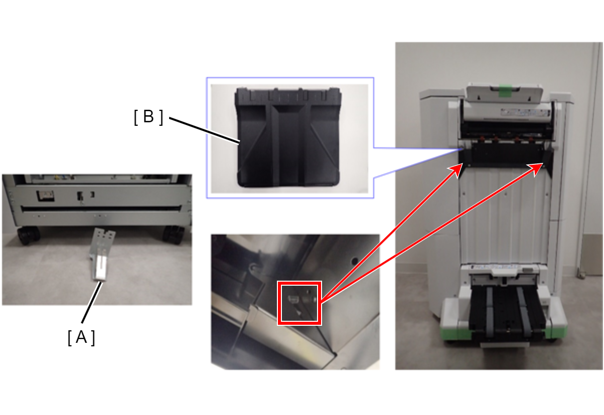
| Prevention of deformation of Bundle Eject Unit
|
| Prevention of breakage of protruding parts
|
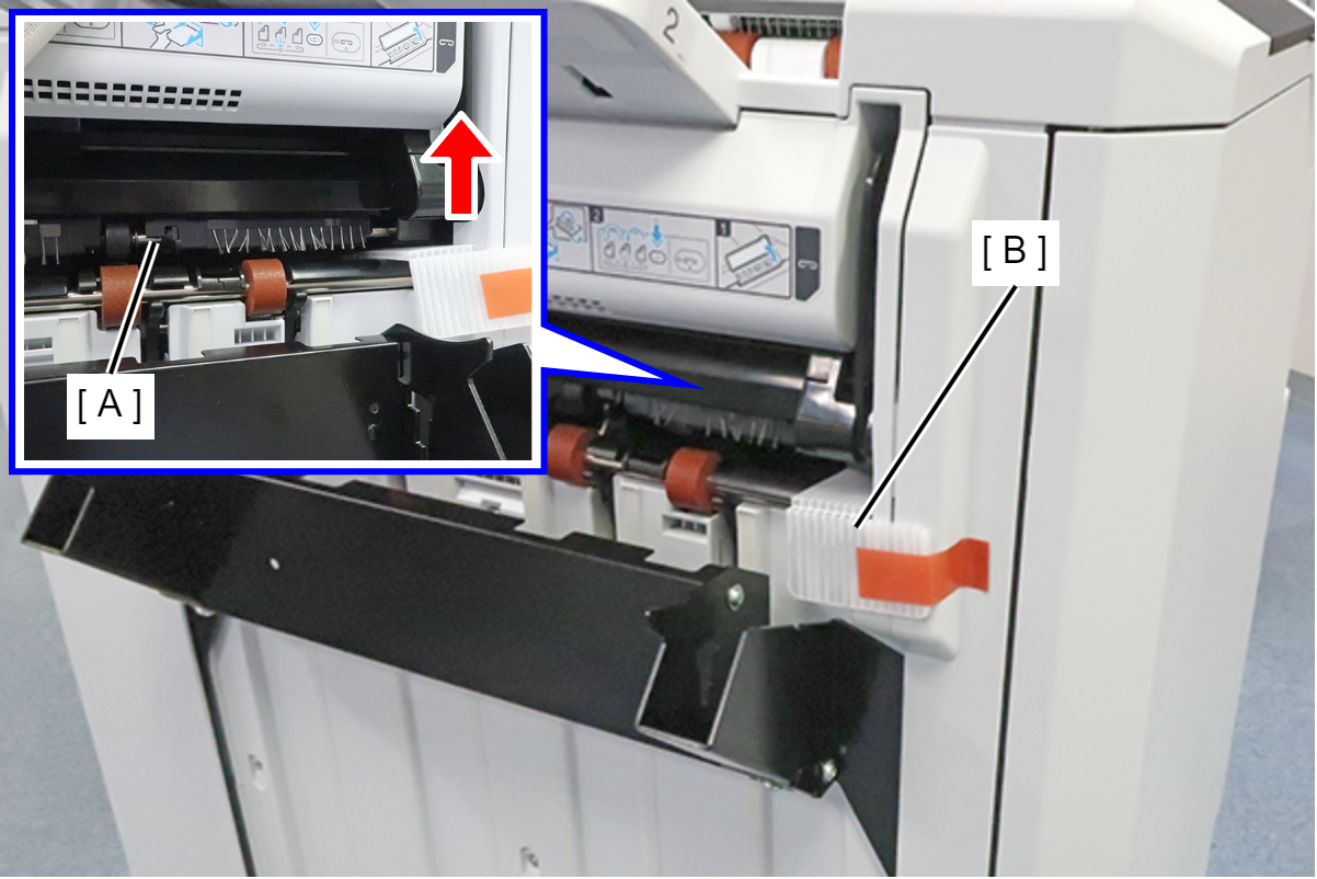
| Preventing moving parts from coming off and popping out
|
| Preventing opening and closing of the paper path of floor bridge unit A
|
| Preventing rubbing between floor bridge unit A and the bottom of the SCN unit
|
| Prevention of deformation of floor bridge unit A, polyester film and finisher connection mechanism
|

Inner Finisher
| Protection Point | Description |
|---|---|
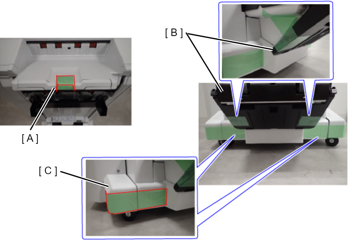
| Preventing the Paper eject tray from falling off
|
Preventing the fixing plate the Paper eject tray from rattling
| |
| Preventing the Inner finisher from sliding
|
| Preventing damage to the main unit and inner finisher Without punch unit:
With punch unit:
|
| Inner bridge exterior cover prevention
|
| ADF/SCN Unit fall prevention
|
High Capacity Unit
| Protection Point | Description |
|---|---|
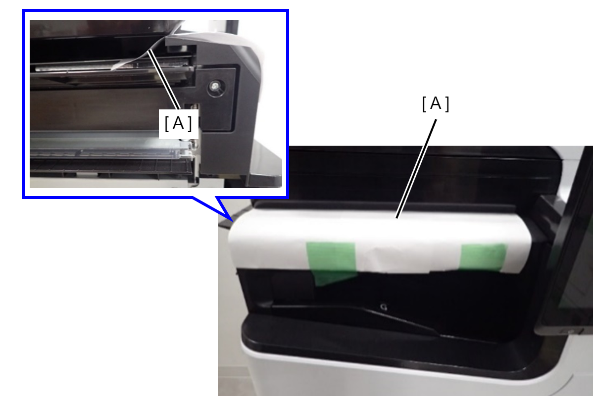
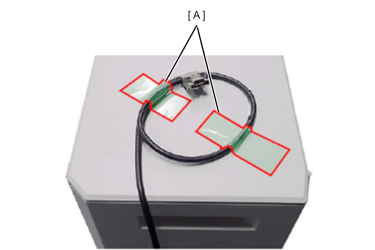
| Cable damage prevention Fix the cable with tape (A). |
Inner Tray
| Protection Point | Description |
|---|---|
| ADF/SCN Unit fall prevention
|